Metal heat shield element with optimized cooling air function

A technology for cooling air and components, used in lighting and heating equipment, combustion methods, continuous combustion chambers, etc., can solve problems such as increased hot air, and achieve the effect of avoiding thermal stress

Active Publication Date: 2018-04-17
SIEMENS ENERGY GLOBAL GMBH & CO KG
View PDF4 Cites 1 Cited by
  • Summary
  • Abstract
  • Description
  • Claims
  • Application Information

AI Technical Summary

Problems solved by technology

[0007] Although the above-mentioned thermal insulation element with cooling air openings arranged in the gaps of the edge sections achieves an improvement with regard to the interception of the gaps for the entry of hot air, however, as occurs in practice, The risk of hot air getting in increases especially at the end of the ventilated edge section

Method used


Image

  • Metal heat shield element with optimized cooling air function
  • Metal heat shield element with optimized cooling air function
  • Metal heat shield element with optimized cooling air function

Examples


Embodiment Construction

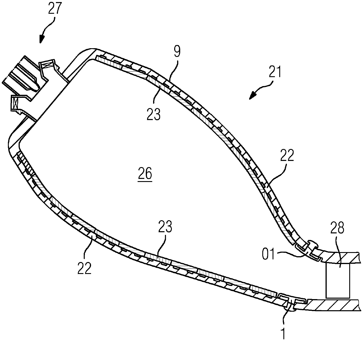
[0038] figure 1 A section through the combustion system of the combustion chamber 26 is shown schematically and by way of example. A burner 27 is arranged in the inlet in the upper region of the combustion chamber 26 . Mixing of fuel and compressed air takes place there. Combustion takes place in the combustion chamber 26 . Through an outlet at the downstream end 24 of the combustor 26 , hot combustion gases enter the turbine where the fuel gases contact a first stationary vane 28 . To prevent fouling, the combustion chamber 26 is lined with ceramic heat insulating tiles 23 and metal heat insulating elements 01 , which are fixed to the load-bearing structure 22 of the heat shield 21 .

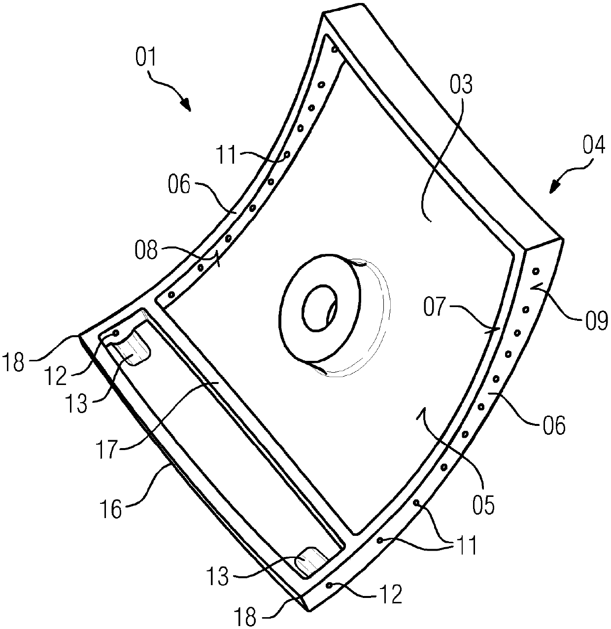
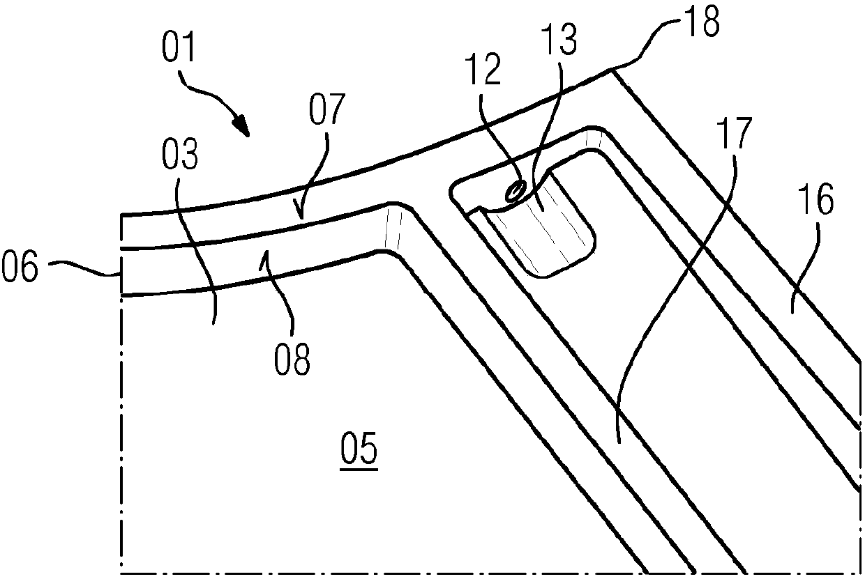
[0039] figure 2 A metal thermal insulation element 01 is shown schematically and by way of example in an embodiment according to the invention, which is used in a heat shield 21 for a combustion chamber 26 of a gas turbine. The thermal insulation element 01 comprises a wall 03 having a ho...


PUM


Abstract

The invention relates to a heat shield element (01) for a heat shield (21) for use in a combustion chamber (26) of a gas turbine. Said heat shield element comprises a wall (03) which has a hot side (04) and a cold side (05) opposite the hot side (04), and mutually opposite first peripheral portions (06) which each extend from the hot side (04) to beyond the cold side (05), and in which peripheralportions (06) a plurality of cooling air openings (11, 12) that are distributed along the length thereof are present. In order to improve the ventilation of the side gap between two heat shield elements (01), at least one cooling air pocket (13) that proceeds from the cold side (05) is present in the wall (03). Said cooling air pocket is in this case arranged in the region of a first cooling air opening (11, 12).

Description

technical field [0001] The invention relates to an insulating element for use in heat shields, in particular for lining combustion chamber walls of gas turbines. Background technique [0002] Very high temperatures occur in the combustion chamber of the gas turbine which, in the absence of effective protective measures, can lead to direct damage to the gas turbine. In a known manner, therefore, a heat shield is used which separates the hot combustion chamber from the structure behind it which is protected against thermal damage. For this purpose, the heat shield is lined with ceramic insulation tiles and / or metal insulation elements. [0003] Insulating tiles or insulating elements generally have a flat or slightly arched shape with a hot side pointing towards the combustion chamber and an opposite cold side and a surrounding edge. They are each fastened to a load-bearing structure arranged below the insulating tile or the insulating element. In a side-by-side multiple ar...

Claims


Application Information

Patent Timeline
IPC IPC(8): F23R3/00
CPCF23R3/002F23R2900/03043F23R2900/03044
Inventor A·伯切尔T·克里格K-U·席尔德马彻
Owner SIEMENS ENERGY GLOBAL GMBH & CO KG
Why Eureka
Try Eureka