

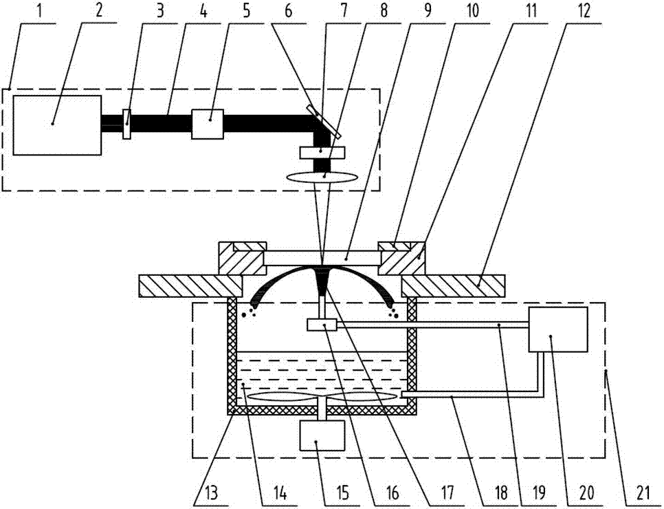
Laser and jet flow compound polishing method and device
A compound polishing and laser polishing technology, which is applied in laser welding equipment, other manufacturing equipment/tools, welding equipment, etc., can solve the problems of low polishing efficiency, low material removal rate, and affecting processing quality, so as to achieve high polishing quality and improve Polishing efficiency, the effect of avoiding thermal stress
- Summary
- Abstract
- Description
- Claims
- Application Information
AI Technical Summary
Problems solved by technology
Method used
Image

Examples
Embodiment 1
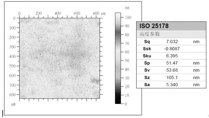
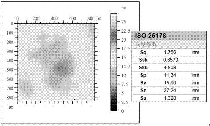
[0048] BK7 with a thickness of 100mm × 100mm and a thickness of 10mm was used as the workpiece 9 to be processed, and its initial surface morphology was measured as figure 2 As shown, the initial surface roughness Sq value is 7.032nm. Select the BK7 workpiece of the same material and size as the spot-collecting part, place it on the positioning plate 11, and fix it by the fixing plate 10, turn on the laser polishing module separately, make the energy modulation of the laser light source 2 the lowest, and focus the laser beam 4 to the sample spot. Spot lower surface. Gradually increase the energy of the laser light source 2, and detect whether the surface shape of the spot-collecting piece changes. If there is no change, the energy of the laser light source 2 is further increased until the surface shape changes, and the parameters of the laser light source at this time are used as the processing parameters in the laser jet composite polishing process.
[0049] Replace the sp...
Embodiment 2
[0052] The implementation steps of this embodiment are basically the same as those in Embodiment 1. The main difference is that the material of the workpiece to be processed is fused silica, the energy of the laser light source in the polishing process is different, and the surface morphology of the fused silica workpiece before composite polishing is as follows: Figure 4 As shown, the surface roughness Sq value is 140.5nm; the surface morphology of the fused silica workpiece after composite polishing is as follows Figure 5 As shown, the surface roughness Sq value is 4.388nm, indicating that the composite polishing method of the present invention effectively improves the surface precision of the fused silica workpiece.
PUM
| Property | Measurement | Unit |
|---|---|---|
| surface roughness | aaaaa | aaaaa |
| surface roughness | aaaaa | aaaaa |
| surface roughness | aaaaa | aaaaa |
Abstract
Description
Claims
Application Information