

Waveguide mode conversion element, orthomode transducer, and optical device
A mode converter and waveguide technology, applied in the field of waveguide mode converters
Active Publication Date: 2016-01-20
NEC CORP
View PDF5 Cites 8 Cited by
- Summary
- Abstract
- Description
- Claims
- Application Information
AI Technical Summary
Problems solved by technology
Also it is necessary to miniaturize the PLC
Method used
View moreImage
Smart ImageViewing Examples

Examples
 PUM
 Abstract
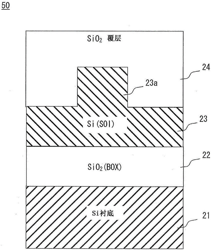
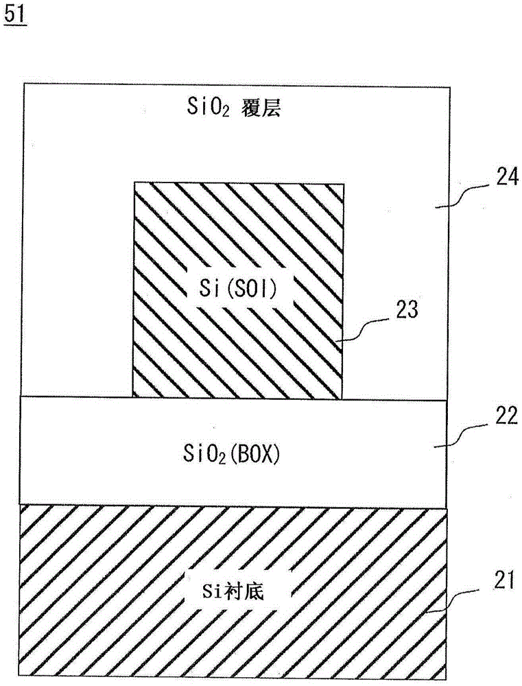
Provided is a waveguide mode conversion element (30) that converts a waveguide mode and that is placed between the transition area (connection section) (43) of a rib-type waveguide (50) and a channel-type waveguide (51). The rib-type waveguide (50) has a tapered section (23b). The tapered section (23b) constitutes a core layer (23) that extends on both sides of a rib (23a) and has a width (Wt) that changes gradually in a direction that is vertical to the waveguide direction.
Description
technical field [0001] The present invention relates to a waveguide mode converter, a polarization beam splitter and an optical device. Background technique [0002] In recent years, transmission methods for optical communication have changed significantly. The transmission method changes from the IM-DD (Intensity Modulation-Direct Detection) method, which has been the main detection method, to a coherent detection method such as QPSK (Quadrature Phase Shift Keying). In the coherent detection method, the DP-QPSK (Polarization Multiplexing-Quadrature Phase Shift Keying) method using orthogonal polarization and phase carrying signals has been researched and developed as a high-speed system for realizing its speed up to 40Gbps or higher than 40Gbps. The transmission method of the transmission, and products using the DP-QPSK method have been shipped locally. [0003] The DP-QPSK method uses a coherent receiver as a main component. The coherent receiver includes a PLC (Planar ...
Claims
Login to View More Application Information
Patent Timeline
 IPC IPC(8): G02B6/14G02B6/122
CPCG02B6/1228G02B6/14G02B6/274G02B6/29355G02B6/2938G02B2006/12097G02B2006/121
Inventor松本崇
OwnerNEC CORP