
Vertical type total knee replacement patella movement test device

A technology of total knee replacement and testing device, which is applied in the direction of joint implants and joint implants, and can solve problems such as joint instability, changing stress distribution on the articular surface, and stress concentration

Inactive Publication Date: 2016-01-27
BEIHANG UNIV
View PDF6 Cites 17 Cited by
  • Summary
  • Abstract
  • Description
  • Claims
  • Application Information

AI Technical Summary

Problems solved by technology

However, the biological structure of the knee joint is complex, and the tibiofemoral and patellofemoral joints are coupled in series. After total knee replacement, the changes in joint material and shape not only affect the kinematic performance of the relationship between the tibiofemoral joint and the patellofemoral joint, but also affect the joint performance after replacement. Stability and dynamic balance, especially the impact on the patellofemoral joint is more obvious, for example: it will change the stress distribution of the articular surface, cause stress concentration or joint instability, and may also change the degree of tightness and stress distribution of the joint ligament. cause ligament damage

Method used


Image

  • Vertical type total knee replacement patella movement test device
  • Vertical type total knee replacement patella movement test device
  • Vertical type total knee replacement patella movement test device

Examples


Embodiment Construction

[0036] Further elaborate the technical scheme of the present invention in conjunction with accompanying drawing:

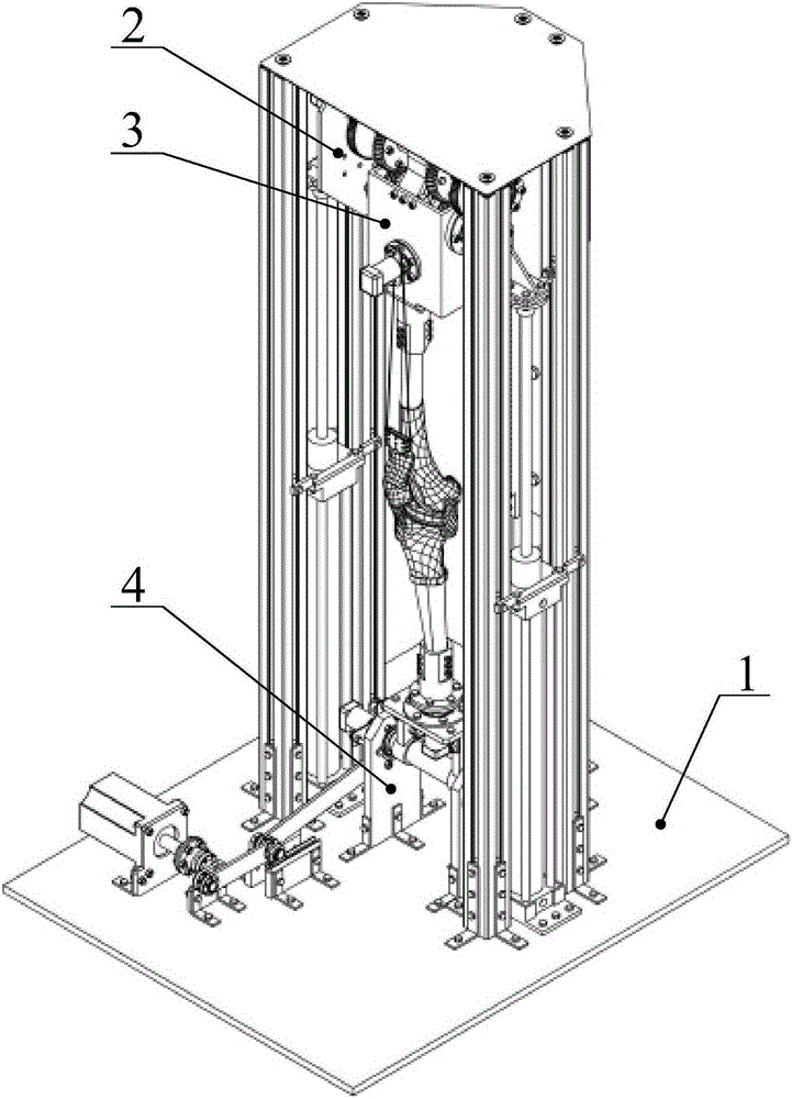
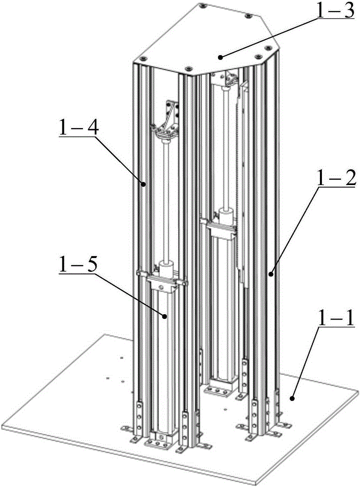
[0037] Such as figure 1 , a kind of vertical total knee replacement joint patella motion testing device of the present invention, it is made up of support structure 1, femur motion mechanism 2, patella motion mechanism 3, tibial motion mechanism and its driving mechanism 4 four parts, the position between them is connected The relationship is: the clamping plate 2-14 of the femoral movement mechanism is connected with the hydraulic cylinder piston rod 1-6 of the support structure, and the rack backing plate 2-12 of the femur movement mechanism is fixed on the aluminum profile column APS-8- On 40801-2, the worm gear box 3-7 of the patellar movement mechanism is connected with the stepped shaft 2-9 of the femoral movement mechanism, the tibial movement mechanism and its driving mechanism are installed on the bottom plate 1-1 of the support structure, and the knee jo...


PUM


Abstract

The invention relates to a vertical type total knee replacement patella movement test device. The vertical type total knee replacement patella movement test device is composed of a supporting structure, a femur movement mechanism, a patella movement mechanism, a tibia movement mechanism and a driving mechanism of the tibia movement mechanism; the supporting structure can realize fixed connection of the test device and movement support of a femur; the movement support is provided by the piston rod of a hydraulic cylinder and is connected with the femur movement mechanism; the femur movement mechanism drives a proximal femur to move up and down and rotate, so that the flexion-extension movement of the femur can be realized; a linkage mechanism of patella and femur movement is adopted, so that patella movement which is coordinated and consistent with the flexion-extension process of the femur can be generated; and the tibia movement mechanism and the driving mechanism thereof are installed at the bottom plate of the supporting structure, and generate flexion-extension movement and self rotation movement of a tibia. According to the vertical type total knee replacement patella movement test device of the invention, the actual movement situation of a replacement prosthesis in the knee of a human being is simulated, so that the movement of the patella can be tested; multiple kinds of movement such as the upward / downward movement of the proximal femur, the flexion-extension movement of the femur, the displacement of patellar ligaments as well as the flexion-extension movement and self rotation movement of the tibia are measured, so that the movement performance of the patella can be obtained.

Description

technical field [0001] The invention relates to a device for testing motion of a total knee joint prosthesis, in particular to a vertical total knee replacement joint patella motion testing device, which belongs to the technical field of medical treatment and medical device design and manufacture. Background technique [0002] As the largest joint in the human body, the knee joint not only supports the weight of the human body but also undertakes the activities of the lower limbs. Because the exposed structure of the knee joint is very easy to damage, and the knee arthritis disease caused by fatigue injury, the cases of knee joint injury and arthritis are increasing rapidly. The ultimate treatment for knee arthritis is total knee replacement. With the aging society, total knee replacement has become the main operation in orthopedic surgery, and its influence is wide and powerful. However, the biological structure of the knee joint is complex, and the tibiofemoral and patell...

Claims


Application Information

Patent Timeline
IPC IPC(8): A61F2/46
Inventor 刘艳强王书楷黄荣瑛龙震张本祥孙亚鹏
Owner BEIHANG UNIV
Learn More