Iron sheet rolling groove winding drum machine

A reeling machine and groove-pressing technology, applied in the direction of heat exchange equipment, etc., can solve problems such as uneven manual force, waste of time, and reduced work efficiency, and achieve the effects of saving labor, ensuring overall quality, and improving production efficiency

Inactive Publication Date: 2016-01-27
JIHUA 3534 CLOTHING
View PDF7 Cites 7 Cited by
  • Summary
  • Abstract
  • Description
  • Claims
  • Application Information

AI Technical Summary

Problems solved by technology

[0002] Because the transformation of the heating pipe network needs to use iron sheets for external insulation to achieve thermal insulation effects, beautiful appearance, and airtightness between the seams. By forming a ring-shaped installation groove at the end of the iron sheet, at present, it is all done manually. To install the heating pipe network, all the pressing grooves and reels need to be done manually. The manual work is extremely labor-intensive and wastes time, resulting in low installation efficiency, and the artificial force is uneven. It will also have different shades and irregular shapes. If the manual force is too strong, the aluminum shell may be deformed or broken. This will not only take time and effort, but also affect the overall quality, reduce work efficiency, and the quality of the finished product is not high. Therefore, It is particularly important to develop a machine for pressing grooves and rolls

Method used


Image

  • Iron sheet rolling groove winding drum machine
  • Iron sheet rolling groove winding drum machine
  • Iron sheet rolling groove winding drum machine

Examples


Embodiment 1

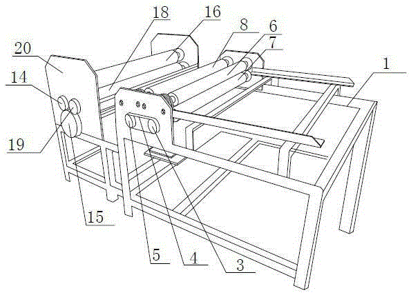
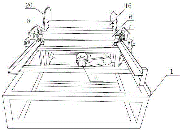
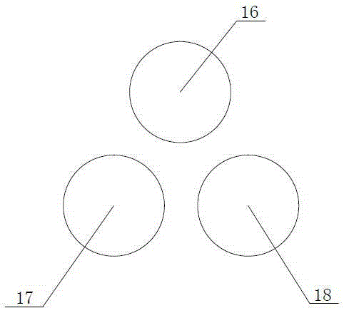
[0018] An iron sheet grooving reel machine, characterized in that it includes a frame 1, a plate feeding mechanism, a grooving mechanism, a reel mechanism and a mechanical transmission mechanism, and the plate feeding mechanism includes an active plate feeding roller 7 and a passive plate feeding pressure roller 7. Roller 6; described groove mechanism comprises pressure groove upper pressure roller 8 and pressure groove lower pressure roller 9, and the both sides of pressure groove upper pressure roller 8 are respectively provided with a pressure groove upper pressure roller 10, and pressure groove lower pressure roller 9 Both sides are respectively provided with a pressure groove lower pressure wheel 11, the pressure groove upper pressure wheel 10 is a convex mode wheel, and the described pressure groove lower pressure wheel 11 is an annular groove wheel, and the convex mode wheel and the annular groove wheel match; The reel mechanism includes the reel upper pressure roller 16...


PUM


Abstract

The invention discloses an iron sheet rolling groove winding drum machine and belongs to the technical field of pipeline processing equipment. The iron sheet rolling groove winding drum machine comprises a machine frame, a plate feeding mechanism, a rolling groove mechanism, a winding drum mechanism and a mechanical driving mechanism. The plate feeding mechanism comprises a driving plate feeding compression roller and a driven plate feeding compression roller. The rolling groove mechanism comprises an upper rolling groove compression roller and a lower rolling groove compression roller. The both sides of the upper rolling groove compression roller are each provided with an upper rolling groove pressing wheel. The both sides of the lower rolling groove compression roller are each provided with a lower rolling groove pressing wheel. The upper rolling groove pressing wheels are terrace die type wheels. The lower rolling groove compression rollers are annular groove wheels. The terrace die type wheels are matched with the annular groove wheels. The winding drum mechanism comprises an upper winding drum compression roller, a winding drum lower left compression roller and a winding drum lower right compression roller. An iron sheet is conveyed through the plate feeding mechanism at first and then is subjected to groove rolling through the rolling groove mechanism, and finally the iron sheet is subjected to winding drum forming through the winding drum mechanism. The iron sheet rolling groove winding drum machine is convenient to operate and capable of saving time, completing operations of transmission, groove rolling and drum winding at a time and saving the manual labor; the installation is convenient, and the production efficiency is improved.

Description

technical field [0001] The invention relates to the technical field of pipeline processing equipment. Background technique [0002] Because the transformation of the heating pipe network needs to use iron sheets for external insulation to achieve thermal insulation effects, beautiful appearance, and airtightness between the seams. By forming a ring-shaped installation groove at the end of the iron sheet, at present, it is all done manually. To install the heating pipe network, all the pressing grooves and reels need to be done manually. The manual work is extremely labor-intensive and wastes time, resulting in low installation efficiency, and the artificial force is uneven. It will also have different shades and irregular shapes. If the manual force is too strong, the aluminum shell may be deformed or broken. This will not only take time and effort, but also affect the overall quality, reduce work efficiency, and the quality of the finished product is not high. Therefore, I...

Claims


Application Information

Patent Timeline
Patent Type & Authority Applications(China)
IPC IPC(8): B21D21/00B21D5/14B21D17/04B21D53/02
Inventor 张金亭宋俊杰吕红杰石杰
Owner JIHUA 3534 CLOTHING
Why Eureka
Try Eureka