Rotary swing block bending and stripping mechanism

A technology for stripping and stripping blocks, applied in metal processing equipment, forming tools, manufacturing tools, etc., can solve the problems of small bending size, inability to process, and stripping of sliders due to thin forming punches, etc., and achieve low cost. , The effect of improving production efficiency and simple structure

Active Publication Date: 2016-01-27
YIHE PRECISION IND SUZHOU
View PDF11 Cites 3 Cited by
  • Summary
  • Abstract
  • Description
  • Claims
  • Application Information

AI Technical Summary

Problems solved by technology

However, the bending size of some products is very small, and the bending part has an inwardly protruding shape, which needs to be avoided on the forming punch, and the conventional slider stripping cannot be processed because the forming punch is too thin

Method used


Image

  • Rotary swing block bending and stripping mechanism
  • Rotary swing block bending and stripping mechanism
  • Rotary swing block bending and stripping mechanism

Examples


Embodiment Construction

[0033] Preferred embodiments of the present invention will be described in detail below in conjunction with the accompanying drawings.

[0034] In order to achieve the purpose of the present invention, in some embodiments of a rotating pendulum block bending and stripping mechanism,

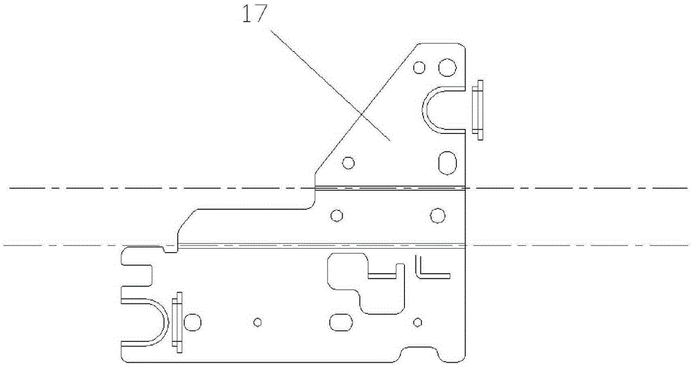
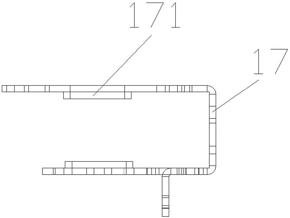
[0035] like figure 1 and 2 are the structural schematic diagrams of the product 17 before and after bending respectively, and the product 17 is according to figure 1 Dotted line in the bend.

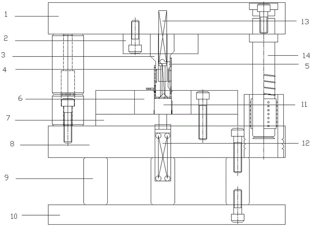
[0036] like image 3 and 4 As shown, a rotating pendulum block bending and stripping mechanism includes: an upper mold base 1 and a lower mold base 8 . image 3 and Figure 4 It is a schematic diagram of a rotating pendulum block bending and stripping mechanism before and after bending the product.

[0037] Forming punch 3 is provided on the upper die base 1, and the molding module is arranged on the upper die base 1 through the upper clamping plate 2, and the stripping pendulum block 5 that is conne...


PUM


Abstract

The invention discloses a rotary swing block bending and stripping mechanism which comprises an upper mould base and a lower mould base, wherein a forming convex mould is arranged on the upper mould base; a stripping swing block which is rotatably connected with the forming convex mould is arranged on the forming convex mould; a notch is formed in the bottom of the forming convex mould and/or the stripping swing block; a forming concave mould is arranged on the lower mould base; a lower mould stripping block is arranged on the forming concave mould; and an ejecting block is arranged on the lower mould stripping block. The rotary swing block bending and stripping mechanism disclosed by the invention can effectively solve an interference problem which is generated in bending and stripping of a product, production efficiency of the product is improved, and the product quality is guaranteed.

Description

technical field [0001] The invention relates to a mold stripping mechanism, in particular to a rotating pendulum block bending stripping mechanism. Background technique [0002] In modern industrial life, many mechanical parts need to be bent. In the bending process, there are manual bending and mold bending. Compared with manual bending, mold bending has the advantages of high efficiency, rapidity, and good precision, and has become the main processing method in bending processing. [0003] In the current mold bending process, the forming punch is generally used to press the parts to be processed, and then extrude to realize the bending deformation. However, the bending size of some products is very small, and the bending part has an inwardly protruding shape, which needs to be avoided on the forming punch, while the conventional slider stripping cannot be processed because the forming punch is too thin. [0004] Therefore, a rotary pendulum bending and stripping mechanis...

Claims


Application Information

Patent Timeline
Patent Type & Authority Applications(China)
IPC IPC(8): B21D37/10B21D45/04
Inventor 占先辉李艳菊
Owner YIHE PRECISION IND SUZHOU
Why Eureka
Try Eureka