Key machining equipment

A processing equipment and key technology, applied in the field of key processing equipment, can solve problems such as poor adjustability and controllability, inability to adjust left and right, and failure to achieve processing effects, and achieve good adjustability and controllability and good market prospects. Effect

Inactive Publication Date: 2016-01-27
SHENZHEN CHUANGDINGFENG TECH CO LTD
View PDF5 Cites 9 Cited by
  • Summary
  • Abstract
  • Description
  • Claims
  • Application Information

AI Technical Summary

Problems solved by technology

[0002] Key processing equipment, also known as key milling machine, is a small lathe used for duplicating keys. In the existing key processing equipment, the fixture can only move back and forth, and cannot be adjusted left and right. Under long-term use, it is difficult to ensure that the milling cutter and probe can Accurately point to the key tee

Method used


Image

  • Key machining equipment
  • Key machining equipment
  • Key machining equipment

Examples


Embodiment 1

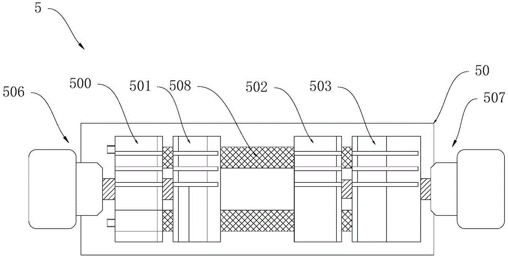
[0041] In this example, combined with Figure 3 to Figure 5 As shown, the clamp assembly 5 includes a clamp support 50, and a first fixed block 500, a first movable block 501, a second fixed block 502 and a second movable block 503 are arranged side by side on the clamp support 50, so that The first fixed block 500 is arranged adjacent to the first movable block 501 and a first jaw 504 for clamping a key is formed between them, and the second fixed block 502 is arranged adjacent to the second movable block 503 And there is formed a second jaw 505 for clamping the key blank between the two, the first fixed block 500 and the second fixed block 502 are fixed on the clamp support 50, and the first fixed block 500 is provided with There is a first locking mechanism 506 for driving the first movable block 501 to reciprocate and slide, and the second fixed block 502 is provided with a second locking mechanism 507 for driving the second movable block 503 to reciprocate and slide. The...

Embodiment 2

[0050] In this example, combined with Figure 6 to Figure 8 As shown, the lifting mechanism 3 is provided with a probe margin adjustment mechanism 30, the probe margin adjustment mechanism 30 includes a sleeve 300, the top of the sleeve 300 is screwed with a plug 301, the The center of the plug 301 is pierced with a telescopic rod 302, the upper end of the plug 301 is provided with an adjustment ring 303, and the adjustment ring 303 is sleeved on the telescopic rod 302, and the edge of the top of the adjustment ring 303 is provided with a relative The first bump 304 and the second bump 305 extend from the bottom of the first bump 304 to the top of the second bump 305 to form a first slope 306, from the bottom of the second bump 305 to the first bump The top of the block 304 is extended to form a second slope 307, and a pin 308 is vertically pierced on the telescopic rod 302, and the two ends of the pin 308 are respectively overlapped on the first slope 306 and the second slope...

Embodiment 3

[0055] In this example, combined with Figure 9 to Figure 11 As shown, the translation mechanism 6 includes two Y-axis sliders 600 fixed on the base 1 in parallel, and the two Y-axis sliders 600 pass through and are slidably connected to a Y-axis slider 601. The Y-axis Two X-axis sliders 602 are fixed in parallel on the slider 601, both of which pass through and are slidably connected to an X-axis slider 603, and a carrier 604 is fixed on the top of the X-axis slider 603 , the stage 604 is used to carry the fixture assembly 5, the side of the base 1 is provided with a rocker 605, the stage 604 is provided with a first universal bearing 606, and the side of the base 1 is provided with The second universal bearing 607, the rocker 605 passes through the first universal bearing 606 and the second universal bearing 607 in turn, and the rocker 605 drives the stage 604 to translate along the X-axis and / or the Y-axis direction .

[0056] In the above translation mechanism, the stage...


PUM


Abstract

The invention discloses key machining equipment. The key machining equipment comprises a base, a machine frame, a lifting mechanism, a driving mechanism, a clamp assembly and a horizontal movement mechanism, wherein the machine frame is arranged on the base; the lifting mechanism is arranged on the machine frame, a milling tool and a probe are arranged on the lifting mechanism side by side, and the lifting mechanism is used for driving the milling tool and the probe to ascend or descend; the driving mechanism is arranged on the machine frame and used for driving the lifting mechanism to slide up and down relative to the machine frame and positioning the lifting mechanism in a preset position; the clamp assembly is arranged below the lifting mechanism and used for clamping a key sample and a key blank; the horizontal movement mechanism is arranged on the base, the clamp assembly is supported on the horizontal movement mechanism, and the horizontal movement mechanism is used for driving the clamp assembly to horizontally move along the X axis and/or the Y axis. The key machining equipment has the beneficial effects of being good in adjustability, good in controllability, convenient to use and the like.

Description

technical field [0001] The invention relates to a small lathe, in particular to a key processing device. Background technique [0002] Key processing equipment, also known as key milling machine, is a small lathe used for duplicating keys. In the existing key processing equipment, the fixture can only move back and forth, and cannot be adjusted left and right. Under long-term use, it is difficult to ensure that the milling cutter and probe can Accurately point to the key teeth. At the same time, the lifting height of the milling cutter and the probe can only be adjusted manually, which lacks positioning and locking functions, so the ideal processing effect cannot be achieved. In combination with the above, it can be seen that the existing key processing equipment has defects such as poor adjustability and controllability. Contents of the invention [0003] The technical problem to be solved by the present invention is to provide a key processing device with good adjustabi...

Claims


Application Information

Patent Timeline
IPC IPC(8): B23C3/35B23Q5/34
Inventor 郭振庄
Owner SHENZHEN CHUANGDINGFENG TECH CO LTD
Why Eureka
Try Eureka