Manufacturing method of drive shaft

A manufacturing method and drive shaft technology, which is applied in the field of drive shaft manufacturing, can solve problems such as shrinking tubes occupying a large area, increasing manufacturing time, and shaft inconsistency, and achieve the effects of reducing investment in production equipment, reducing bending, and reducing weight

Active Publication Date: 2017-12-12
郑锺勋
View PDF7 Cites 0 Cited by
  • Summary
  • Abstract
  • Description
  • Claims
  • Application Information

AI Technical Summary

Problems solved by technology

[0009] However, as mentioned above, when reducing the diameter of the metal tube formed with the strength-reduced portion by using a plurality of shrinking dies with gradually smaller diameters, the manufacturing time is greatly increased. occupies a large area
[0010] In addition, when using multiple shrinking molds to shrink the tube, due to the force applied along the axial direction of the metal tube, the axis of the metal tube is twisted or the axis of the shrunk part and the unshrunk part are inconsistent.
[0011] In addition, since the tube is shrunk while applying force in the axial direction of the metal tube, too much force is also applied in the axial direction of the metal tube, so that there is a possibility that the shrinking part and the non-shrinking part may be damaged. Severe cracks develop between parts of the

Method used


Image

  • Manufacturing method of drive shaft
  • Manufacturing method of drive shaft
  • Manufacturing method of drive shaft

Examples


Embodiment Construction

[0055] Hereinafter, embodiments of the present invention will be described in detail with reference to the accompanying drawings. In this process, the size and shape of members shown in the drawings may be exaggerated for convenience and clarity of description. In addition, terms specifically defined in consideration of the constitution and operation of the present invention may be different depending on the user's or operator's intention or practice. The definitions of these terms should be interpreted based on the meaning and concept of the technical idea of ​​the present invention based on the entire content of this specification.

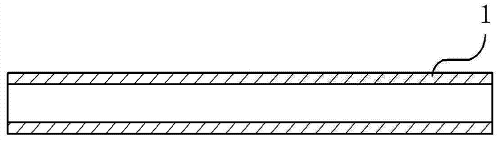
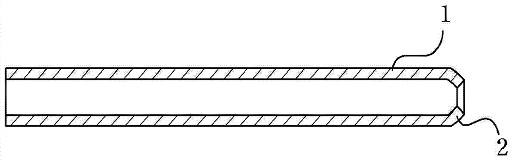
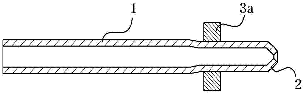
[0056] Figure 1a 6 is a cross-sectional view and an enlarged view of the manufacturing process of the drive shaft according to the embodiment of the present invention.

[0057] Figure 1aA cross-section of the metal tube used to make the drive shaft.

[0058] Such as Figure 1a As shown, the metal tube 1 used to manufacture the drive shaft is...


PUM


Abstract

The method for manufacturing a drive shaft of the present invention includes: uniformly shrinking one side of a metal tube having a first strength to form a first shaft portion; drawing the metal tube integrally formed with the first shaft portion The central part of the above-mentioned step of reducing the thickness of the central part; heat-treating the inner surface of the other side opposite to the above-mentioned one side of the above-mentioned metal tube according to a certain length, so as to form an inner surface of the other side of the above-mentioned metal tube. a step of reducing the strength of the second strength lower than the first strength; and shrinking the metal tube on which the strength reducing portion is formed so as to form the second shaft portion without deforming the shape of the central portion Step; wherein, the second shaft portion is formed by applying a compressive force to a portion of the metal pipe where the strength reducing portion is formed in a direction perpendicular to the axial direction of the metal pipe.

Description

technical field [0001] The invention relates to a manufacturing method of a drive shaft, which prevents bending and shape deformation of the metal tube that occurs when the metal tube is shrunk to form a drive shaft, reduces weight, suppresses vibration, reduces production cost and investment in production equipment, and prevents damage to the drive shaft. The bending of the shaft during shrinkage of the metal tube. Background technique [0002] Generally speaking, in the case of a rear-wheel drive or four-wheel drive vehicle, the engine output of the vehicle is transmitted to the differential gear of the vehicle through the transmission and the drive shaft connected to the transmission, and the output of the vehicle is transmitted to the rear wheels through the differential gear. The power travels in rear-wheel drive or four-wheel drive. [0003] Here, since the torsional stress received by the drive shaft that transmits the power of the transmission to the differential ge...

Claims


Application Information

Patent Timeline
Patent Type & Authority Patents(China)
IPC IPC(8): B23P15/00
Inventor 郑锺勋金东建
Owner 郑锺勋
Why Eureka
Try Eureka