Conveying device for magnetic ring

A technology of magnetic rings and driving devices, which is applied in the direction of coating, etc., can solve the problems of increased labor costs, low work efficiency, and low stability, and achieve the effects of reducing labor intensity, improving production efficiency, and accurate positioning

Active Publication Date: 2016-01-27
江门协立磁业高科技有限公司
View PDF5 Cites 4 Cited by
  • Summary
  • Abstract
  • Description
  • Claims
  • Application Information

AI Technical Summary

Problems solved by technology

[0004] Using this method of manual feeding, the work efficiency is low, the stability is not high, and it is necessary to specially arrange workers to complete this work, which will also increase labor costs.

Method used


Image

  • Conveying device for magnetic ring

Examples


Embodiment Construction

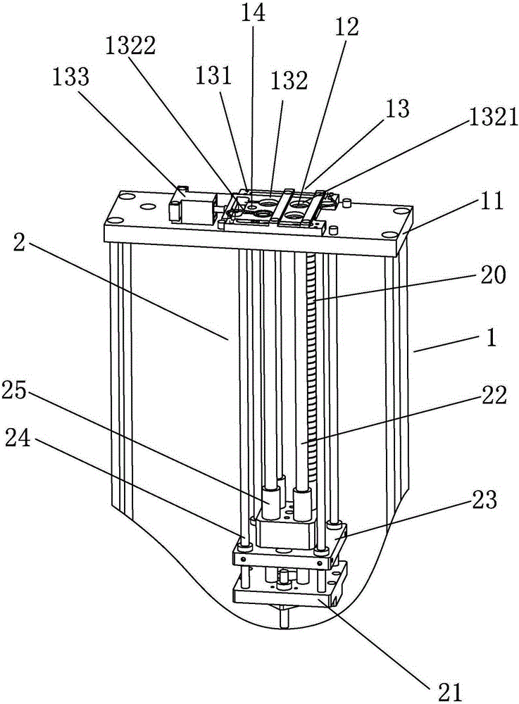
[0016] refer to figure 1 , a magnetic ring feeding device, comprising a material retrieving support 1 and a material rack 2 for placing a magnetic ring 20, the retrieving support 1 includes a retrieving positioning plate 11 positioned above the material rack 2 and a retrieving positioning plate 11 mounted on the retrieving positioning plate 11 The dislocation mechanism 13 on the top, the dislocation mechanism 13 includes a guide rail 131 and a dislocation plate 132 that can translate along the guide rail 131 on the reclaiming positioning plate 11, and one end of the dislocation plate 132 is connected with a 13 translational driving device 133, the material rack 2 includes a lower plate 21 that can move up and down, and the lower plate 21 is vertically installed with a discharge column 22 for placing the magnetic ring 20 upwards. The number of discharge columns 22 in the present invention is four The retrieving positioning plate 11 is provided with a through hole 12 at a positi...


PUM


Abstract

The invention discloses a conveying device for a magnetic ring. The device comprises a material picking support, and a material rack for positioning the magnetic ring, wherein the material picking support comprises a material picking positioning plate positioned above the material rack, and a staggering mechanism mounted on the material picking positioning plate; the staggering mechanism comprises a guide rail, and a staggering plate which can translate on the material picking positioning plate along the guide rail; a driving device, which is mounted on the material picking positioning plate and can drive the staggering mechanism to translate, is connected to one end of the staggering plate; the material rack comprises a lower plate which can move up and down; the lower plate is upwards vertically equipped with a material positioning column for positioning the magnetic ring; a through hole is formed in a position, corresponding to the material positioning column, on the material picking positioning plate; a staggering hole fitting the through hole is formed in the staggering plate; an upper plate for pushing the magnetic ring to raise and driving the magnetic ring to enter the through hole as well as the staggering hole movably passes through the material positioning column. With the adoption of the device, the magnetic ring can be quickly and accurately conveyed to the position where a manipulator can capture the magnetic ring as requirement, so that the labor intensity of workers can be reduced; adjacent magnetic rings can be effectively prevented from being synchronously picked out; the production efficiency can be improved.

Description

technical field [0001] The invention relates to a magnetic ring feeding device. Background technique [0002] At present, magnetic rings are inlaid in many injection molding magnets. During manufacturing, the magnetic rings are usually placed in the injection molding machine by hand, and then injected to make the magnetic rings embedded in the plastic parts. [0003] Due to the mutual attraction between the adjacent magnetic rings, it is easy to take out the adjacent magnetic rings when taking out the uppermost magnetic ring of the discharging column. [0004] Using this method of manual feeding has low work efficiency and low stability, and it is necessary to specially arrange workers to complete this work, which will also increase labor costs. Contents of the invention [0005] In order to overcome the deficiencies of the prior art, the present invention provides a magnetic ring feeding device with high working efficiency and accurate material feeding. [0006] The tec...

Claims


Application Information

Patent Timeline
Patent Type & Authority Applications(China)
IPC IPC(8): B29C45/14
CPCB29C45/14008B29C45/14778
Inventor 林炳炎林国盛朱炳财梁洪达
Owner 江门协立磁业高科技有限公司
Why Eureka
Try Eureka