Crankshaft or connecting rod bearing units for internal combustion engines

A technology for connecting rod bearings and internal combustion engines, applied in connecting rod bearings, crankshaft bearings, bearing assembly, etc., can solve problems such as bearing device friction, and achieve the effect of small bearing friction and high stability

Active Publication Date: 2019-02-05
AB SKF
View PDF9 Cites 0 Cited by
  • Summary
  • Abstract
  • Description
  • Claims
  • Application Information

AI Technical Summary

Problems solved by technology

[0004] The disadvantage is that bearing arrangements in this way sometimes have significant friction
Furthermore, the stability of the bearing arrangement is not always optimal

Method used


Image

  • Crankshaft or connecting rod bearing units for internal combustion engines
  • Crankshaft or connecting rod bearing units for internal combustion engines
  • Crankshaft or connecting rod bearing units for internal combustion engines

Examples


Embodiment Construction

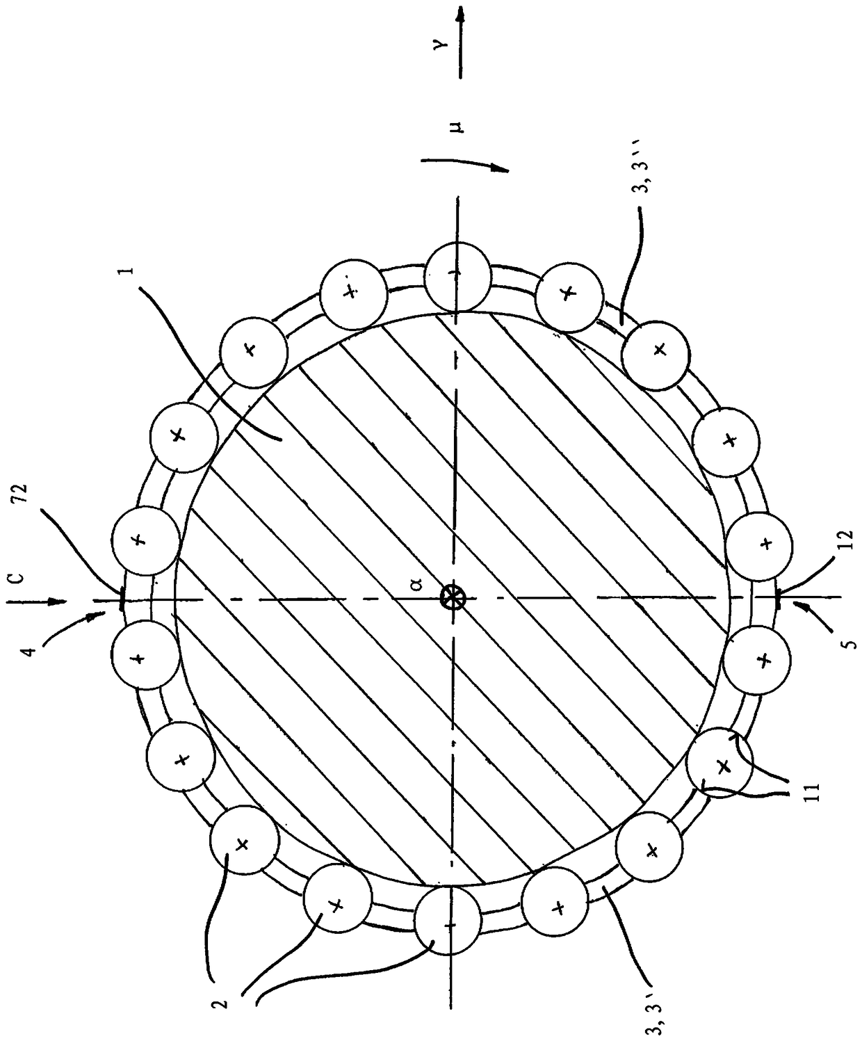
[0024] exist figure 1 shows an axial section through the journal 1 of the crankshaft of the internal combustion engine. The journal 1 of the crankshaft and the row of rolling elements which surround the journal 1 are visible. The individual rolling elements 2 are secured by a cage 3 which in the present exemplary embodiment consists of two cage segments 3 ′ and 3 ″. The two cage segments 3 ′ and 3 ″ are butted together at two abutment points 4 and 5 , which are diametrically opposite on the journal 1 . The two abutment points 4 and 5 are therefore offset by 180° in the circumferential direction U. Also documented are the radial direction r and the axial direction a, where the latter is in figure 1 perpendicular to the plane of the drawing.

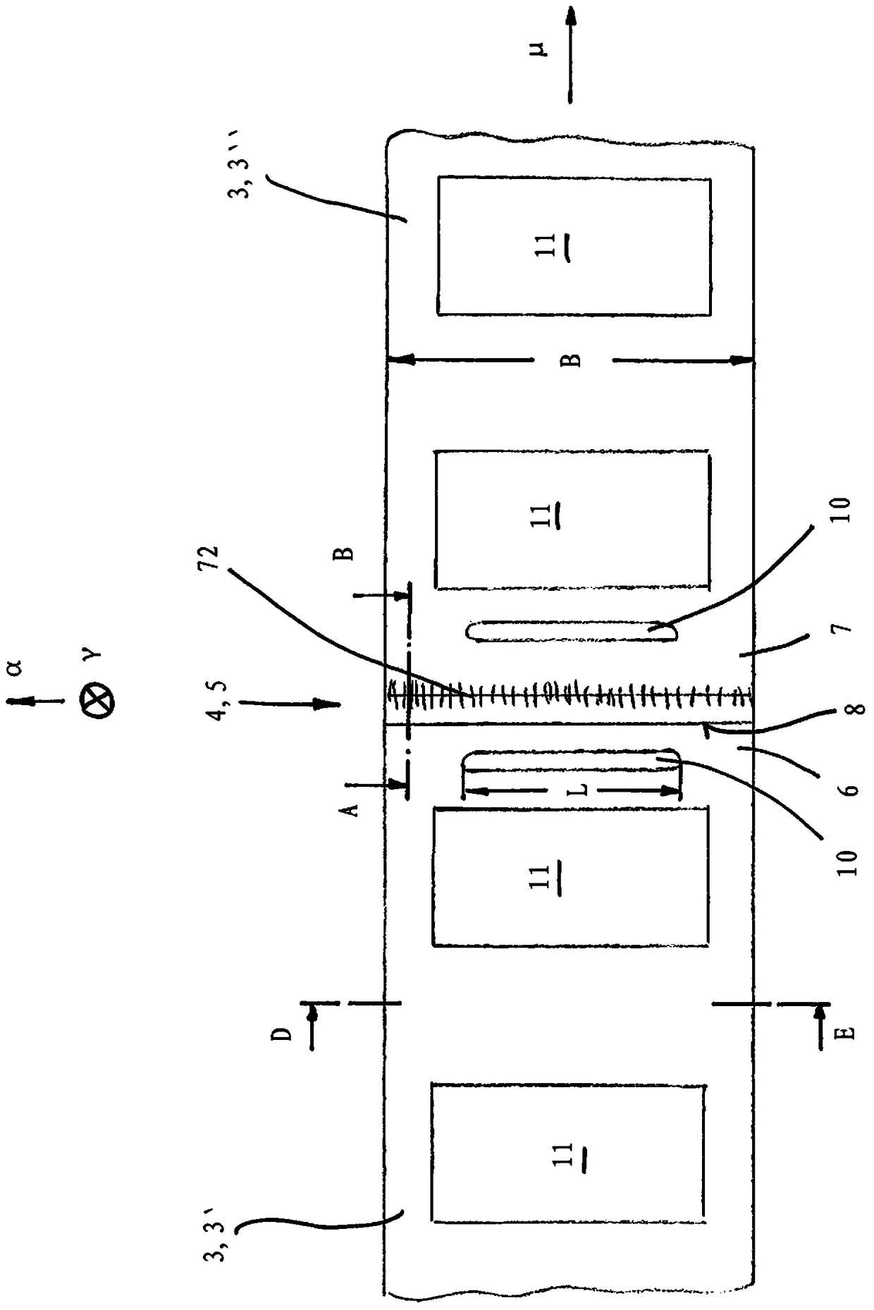
[0025] The two cage segments 3' and 3'' have a plurality of receiving pockets 11 into which the rolling elements 2 are respectively inserted.

[0026] look at figure 2 and 4 It can be seen that the two cage segments 3 ′ and 3 ″ are...


PUM


Abstract

The invention relates to a crankshaft or connecting rod bearing arrangement for an internal combustion engine, the bearing arrangement having a journal (1) serving as an inner bearing ring and an outer bearing ring surrounding the journal (1), wherein the journal (1) and At least one row of rolling elements (2) is arranged between the outer rings of the bearing, wherein the rolling elements (2) are held by a cage (3), and wherein the cage (3) is composed of at least two cage segments (3', 3) ``), the two cage segments respectively extend around the circumferential section of the journal (1). In order to ensure a low-friction and stable bearing of the journals or connecting rods, the invention provides that at least two cage segments (3', 3") are connected to each other at at least one abutment point (4, 5) located in the circumferential direction. Material joint connection.

Description

technical field [0001] The invention relates to a crankshaft or connecting rod bearing arrangement of an internal combustion engine, the crankshaft or connecting rod bearing arrangement having a journal serving as a bearing inner ring and a bearing outer ring surrounding the journal, wherein between the journal and the bearing outer ring At least one row of rolling bodies is provided, wherein the rolling bodies are held by a cage, and wherein the cage consists of at least two cage segments which each extend around a circumferential section of the journal. Background technique [0002] Generally, the journal of the crankshaft and the connecting rod are supported on the crankshaft by means of sliding bearings; of course, rolling bearing arrangements can also be used on this bearing location. For guiding the rolling bodies, cage segments are used in this case which hold the rolling bodies and which are arranged between the journal to be supported and the surrounding housing ser...

Claims


Application Information

Patent Timeline
Patent Type & Authority Patents(China)
IPC IPC(8): F16C33/46F16C9/02F16C33/56F16C33/50
CPCF16C9/00F16C19/463F16C33/504F16C33/542F16C2226/36F16C19/26F16C33/547F16C9/02F16C9/04
Inventor R.哈斯Y.凯勒A.奥尔舍韦斯基V.文特
Owner AB SKF
Why Eureka
Try Eureka