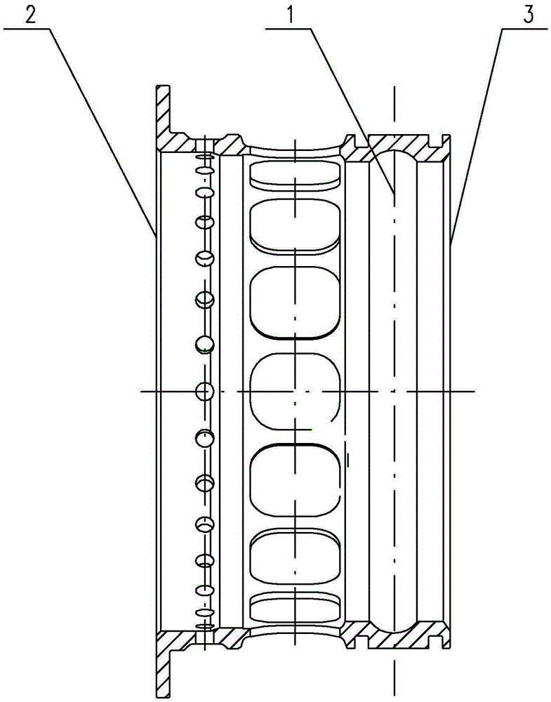
Measuring method for squirrel cage elastic support ball bearing outer ring groove position and precision
A kind of technology of bearing outer ring and measurement method, applied in the direction of measurement device, instrument, etc., can solve the problem of measurement of channel size and accuracy, and achieve the effect of simple operation, guaranteeing the factory pass rate and accurate measurement
- Summary
- Abstract
- Description
- Claims
- Application Information
AI Technical Summary
Problems solved by technology
Method used
Image
Examples
specific Embodiment approach 1
[0024] Specific implementation mode 1: Combination figure 1 To illustrate this embodiment, the method for measuring the position of the outer ring groove of a squirrel cage ball bearing described in this embodiment includes the following steps:
[0025] Step 1: Select a measuring instrument: According to the size of the bearing structure, use the D012 or D013 bearing special measuring instrument to measure the position and accuracy of the groove center 1 to the non-reference end surface 3, and use the G904 or G905 bearing special measuring instrument to measure the total bearing outer ring For the size of height H, select an instrument that meets the measurement accuracy according to the accuracy requirements;
[0026] Step 2: Measure the total height of the outer ring of the bearing: use the selected special measuring instrument to measure the distance between the reference end surface 2 and the non-reference end surface 3 of the bearing, that is, the total height H of the outer r...
specific Embodiment approach 2
[0032] Specific implementation manner two: combination figure 1 To explain this embodiment, in step 2 of this embodiment, when the height h between the channel center 1 and the reference end surface 2 is qualified, the tolerance of the total height H of the outer ring of the bearing needs to be measured, and it is performed in step 4 When calculating the height h between the channel center 1 and the reference end surface 2, the tolerance of the total height H of the outer ring of the bearing is included in formula 1. The technical features not disclosed in this embodiment are the same as those in the first embodiment.
[0033] For the first product that is qualified to be processed, the standard true value of the height h1 between the channel center 1 and the non-reference end surface 3 is obtained as a standard part by the method of the first embodiment, and the subsequent processing product is between the channel center 1 and the reference end surface 2 The height h of the spa...
specific Embodiment approach 3
[0036] Specific implementation mode three: combination figure 1 To explain this embodiment, the tolerance range of the total height H of the outer ring of the bearing in this embodiment is controlled within 0.004 mm. The technical features not disclosed in this embodiment are the same as those in the second embodiment.
[0037] The smaller the tolerance range of the total height H of the outer ring of the bearing, the better. This design facilitates the control of the dimensional difference between the channel center 1 and the reference end surface 2.
PUM
 Abstract
Description
Claims
Application Information
 - R&D
- Intellectual Property
- Life Sciences
- Materials
- Tech Scout
- Unparalleled Data Quality
- Higher Quality Content
- 60% Fewer Hallucinations
Browse by: Latest US Patents, China's latest patents, Technical Efficacy Thesaurus, Application Domain, Technology Topic, Popular Technical Reports.
© 2025 PatSnap. All rights reserved.Legal|Privacy policy|Modern Slavery Act Transparency Statement|Sitemap|About US| Contact US: help@patsnap.com

