Arc angle laser welding forming method of angle seam joints

A technology of laser welding and forming method, applied in laser welding equipment, welding equipment, metal processing equipment and other directions, can solve the problems of easy formation of undercut defects, reduce production efficiency, increase workload, etc., to eliminate differences in professional quality, achieve Automated production to ensure the effect of the appearance of the weld

Inactive Publication Date: 2018-07-27
WUHAN HGLASER ENG CO LTD
View PDF3 Cites 5 Cited by
  • Summary
  • Abstract
  • Description
  • Claims
  • Application Information

AI Technical Summary

Problems solved by technology

[0004] 1) Due to the large heat input of argon arc welding, the workpiece will be severely deformed, and time-consuming and labor-intensive artificial correction is required after welding;
[0005] 2) The heat-affected zone of argon arc welding is large, and the color of the base metal around the weld will change, which must be polished or pickled, which greatly increases the workload;
[0006] 3) The welding seam of argon arc welding is high and must be polished. This link will greatly increase labor costs and will drastically reduce production efficiency;
[0007] 4) Due to the difference in the professionalism of the operators, argon arc welding will lead to problems such as insufficient weld strength and a large number of defects. It needs to be repaired and even scrapped, which wastes manpower and material resources;
[0008] 5) The argon arc welding environment is relatively harsh, which will cause great harm to the human body
[0010] 1) Due to the small diameter of the spot (the diameter of the focused spot is 0.3mm to 0.8mm), it is easy to form a weld with a large depth-to-width ratio, and the appearance is not uniform enough and the texture is rough, which cannot meet the appearance requirements of the workpiece;
[0011] 2) Due to the small diameter of the spot, the molten base metal is less during welding, and the weld pool of self-fluxing welding cannot completely cover the seams of the two plates A and B, resulting in the formation of undercut defects

Method used


Image

  • Arc angle laser welding forming method of angle seam joints
  • Arc angle laser welding forming method of angle seam joints
  • Arc angle laser welding forming method of angle seam joints

Examples


Embodiment 1

[0043] Such as Figure 1-Figure 5 , an embodiment of the present invention provides a circular arc angle laser welding forming method for corner seam joints, including:

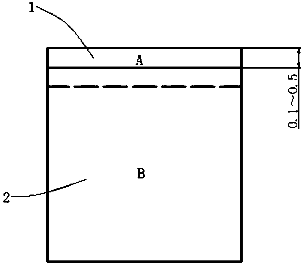
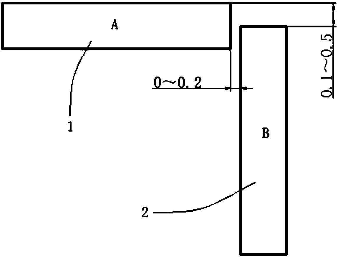
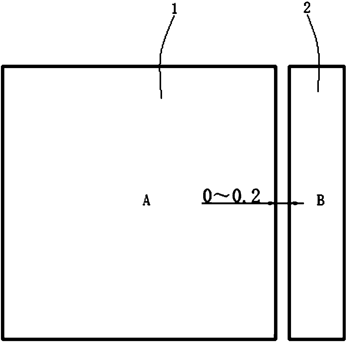
[0044] Position the two plates so that plate A 1 and plate B 2 are perpendicular to each other and the distance between them is controlled within the range of 0-0.2 mm. The end surface of plate B 2 to be welded is located between the two plates of plate A 1 The distance between the outer surfaces of the board A 1 is 0.1-0.5mm; it is welded and formed by laser self-fusion welding, wherein the focused spot diameter of the laser beam is 1.5-2.2mm.

[0045] It is easy to know that the distance between the A board 1 and the B board 2 refers to the distance between the end to be welded of the A board 1 and the adjacent board surface of the B board 2; The board surface is located between the planes of the two board surfaces of A board 1. Correspondingly, one of the board surfaces of A board 1 is located between the...

Embodiment 2

[0065] The embodiment of the present invention provides a method for arc angle laser welding of corner seam joints. In the corner seam joints, the base material is stainless steel with a thickness of 1 mm. Plate A 1 is arranged horizontally, and plate B 2 is arranged vertically. When assembling, ensure that the horizontal distance between the two boards is controlled at about 0.05mm, and the distance between the top of B board 2 and the upper surface of A board 1 is about 0.2mm; use a coaxial shielding gas with a nozzle diameter of 8mm to protect the weld seam, and weld The distance between the gas nozzle and the welding seam plane is 5mm, the shielding gas is Ar with a purity of 99.999%, and the pressure of the shielding gas at the gas cylinder outlet is 0.1MPa; the incident angle of the laser beam relative to the surface of A-plate 1 is 4°; Welding parameters choose laser power 2000w, welding speed 45mm / s, spot diameter 2.0mm. When welding, use the left welding method ( Fi...

Embodiment 3

[0067] An embodiment of the present invention provides a method for arc angle laser welding of a corner joint. The base material of the corner joint is stainless steel with a thickness of 0.7 mm. Plate A 1 is arranged horizontally, and plate B 2 is arranged vertically; When assembling, ensure that the horizontal distance between the two boards is 0 (that is, the end to be welded of A board 1 is in contact with B board 2), and the distance between the top of B board 2 and the upper surface of A board 1 is about 0.1mm; use the air nozzle A coaxial shielding gas shielded weld with a diameter of 6mm, the distance between the gas nozzle and the weld plane is 3mm during welding, the shielding gas uses Ar with a purity of 99.999%, and the pressure of the shielding gas at the gas cylinder outlet is 0.05MPa; the laser beam is relatively The incident angle on the surface of A board 1 is 0; the welding parameters are selected as laser power 1500w, welding speed 50mm / s, and spot diameter 1...


PUM

PropertyMeasurementUnit
diameteraaaaaaaaaa
angle of incidenceaaaaaaaaaa
thicknessaaaaaaaaaa

Abstract

The invention relates to an arc angle laser welding forming method of angle seam joints. The method comprises the steps as follows: two plates are positioned, the plate A and the plate B are perpendicular, the distance between the two plates is controlled within the range of 0-0.2 mm, the to-be-welded end surface of the plate B is located between two plate surfaces of the plate A, and the distancebetween the to-be-welded end surface of the plate B and the outer side plate surface of the plate A is in a range of 0.1-0.5 mm; a laser self-fusion welding manner is adopted for welding forming, andthe focus spot diameter of laser beams is 1.5-2.2 mm. A special welding joint splicing form is adopted, the space occupied by surplus height of appropriate weld seams is reserved, the weld seams haverelatively flat surfaces after welding and form smooth arc angle seams, the weld seam appearance requirement is guaranteed, and the weld seam arc angle forming requirement can be better met; a large-focus spot diameter laser welding technology is adopted, welding seam forming can meet the product requirement, simple polishing treatment is needed only in the later period, and stable production with high quality, efficiency and benefits is realized.

Description

technical field [0001] The invention belongs to the technical field of laser welding, and in particular relates to an arc angle laser welding forming method for corner seam joints. Background technique [0002] Corner seam joints are widely used in high-end handicrafts, kitchen and bathroom appliances (including hoods, stoves, towel racks, etc.), food processing, household appliances, etc., and a basic requirement in these industries is that the appearance must be good-looking , Good-looking, so the appearance requirements of these fillet joints are extremely strict. Generally, it is required that the workpiece has no deformation after welding, the weld seam is uniform and smooth, the weld seam has no collapse and no obvious reinforcement, the heat-affected zone of the weld seam is small, and the strength is high enough. [0003] For such high-demand fillet joints, the traditional manufacturing process uses argon arc welding for welding and then post-processing. This manufac...

Claims


Application Information

Patent Timeline
Patent Type & Authority Applications(China)
IPC IPC(8): B23K26/21B23K26/70
CPCB23K26/21B23K26/702
Inventor 吴泽锋祁小勇余世文叶兵王爱华
Owner WUHAN HGLASER ENG CO LTD
Why Eureka
Try Eureka