Image forming apparatus and exposure position adjustment method

An image and line image technology, which is applied in the field of image forming device and exposure position adjustment, can solve problems such as bad image, inability to purely distinguish and adjust beam spacing, etc., and achieve the effect of suppressing process noise

Inactive Publication Date: 2018-01-30
KONICA MINOLTA INC
View PDF8 Cites 0 Cited by
  • Summary
  • Abstract
  • Description
  • Claims
  • Application Information

AI Technical Summary

Problems solved by technology

[0019] However, if Figure 10 As shown, if there is process noise such as black stripes 304B at the position to be determined (the border of the repeated line image) indicated by the arrow, accurate determination cannot be made.
[0020] Any of the techniques described in the above-mentioned Patent Documents 1 to 3 relate to the formation of an evaluation chart for judging the quality of the beam pitch in the sub-scanning direction, and do not perform automatic correction of the beam pitch.
In addition, even if this evaluation chart is used, it is not possible to purely identify and adjust the deviation of the beam pitch due to the influence of process noise generated after exposure.
Therefore, even if the beam pitch is adjusted based on these evaluation charts, there is a possibility that defective images may occur due to subsequent process fluctuations.

Method used


Image

  • Image forming apparatus and exposure position adjustment method
  • Image forming apparatus and exposure position adjustment method
  • Image forming apparatus and exposure position adjustment method

Examples


no. 1 approach >

[0039] [Configuration Example of Image Forming Apparatus]

[0040] First, refer to figure 1 The outline of the image forming apparatus according to one embodiment of the present invention will be described.

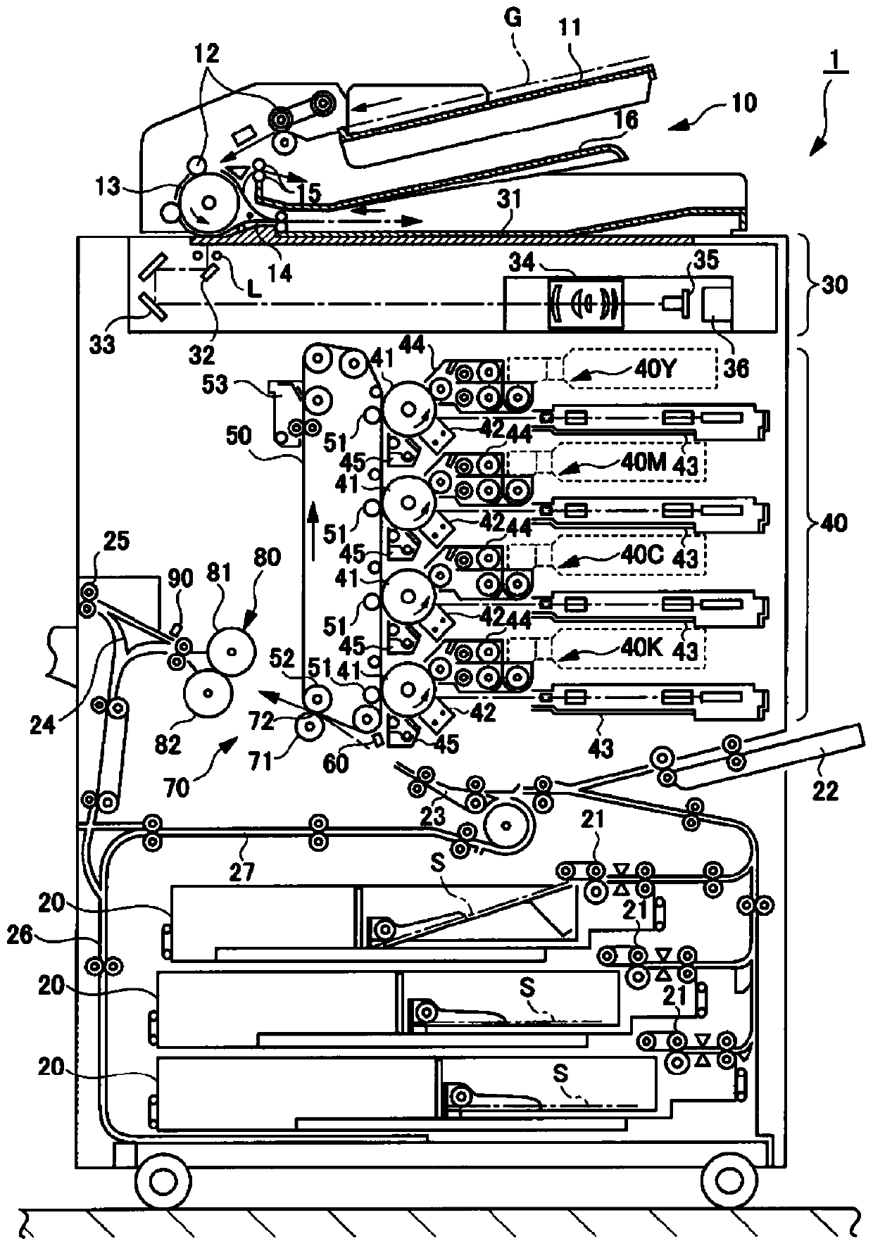
[0041] figure 1 It is a diagram showing the overall configuration of an image forming apparatus according to an embodiment of the present invention.

[0042] Such as figure 1As shown, the image forming apparatus 1 forms an image on a sheet of paper by electrophotography, and is in a serial form in which four color toners of yellow (Y), magenta (M), cyan (C) and black (Bk) are superposed. color image forming device. The image forming apparatus 1 includes a document conveyance unit 10 , a paper storage unit 20 , an image reading unit 30 , an image forming unit 40 , an intermediate transfer belt 50 , a secondary transfer unit 70 , and a fixing unit 80 .

[0043] The document transport unit 10 has a document feed table 11 on which a document G is placed, a plurality o...

no. 2 approach >

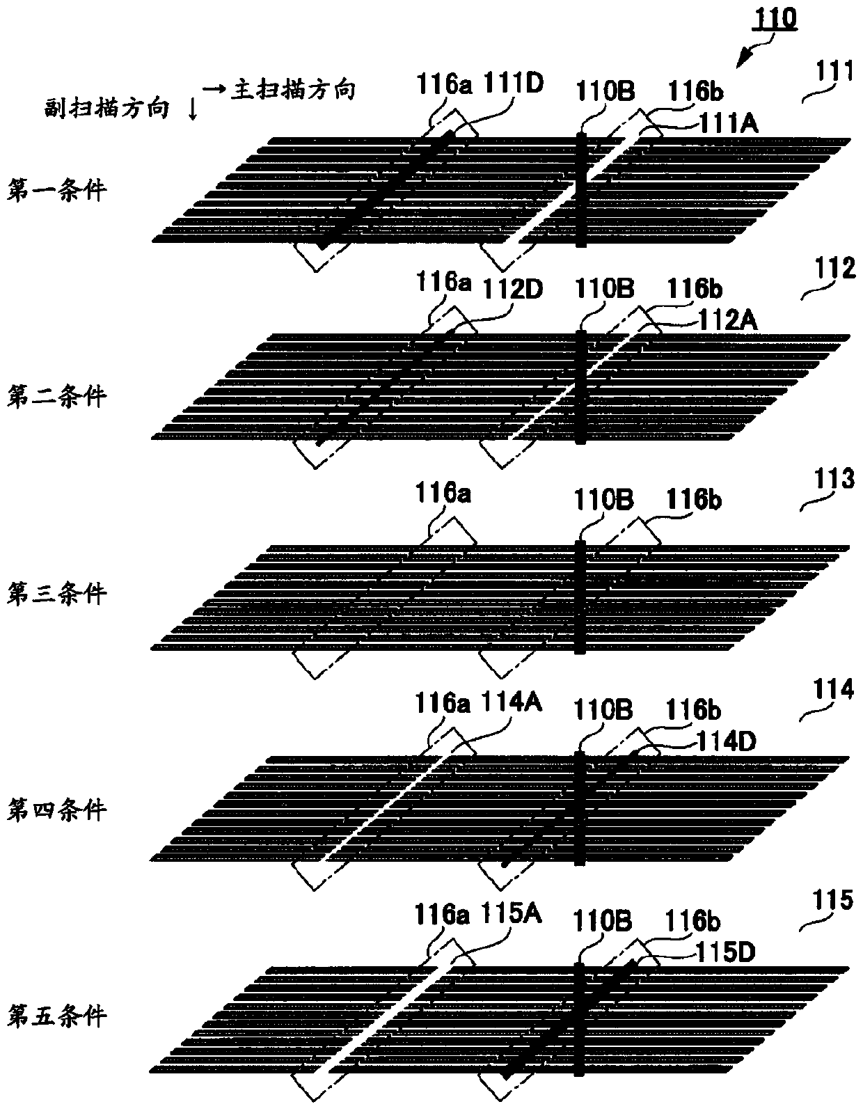
[0119] In the above-mentioned first embodiment, the pattern image 110 is deformed, and the inspection regions 116a and 116b are used as vertical image information, and the non-inspection region 117 is used as oblique image information. However, no deformation processing may be performed. That is, in the second embodiment, the exposure position adjustment process is performed with the inspection regions 116 a and 116 b tilted.

[0120] Figure 8 A pattern image according to the second embodiment of the present invention is shown. The pattern image 130 is formed with image 3 Similarly, the pattern image 130 is exposed using LD1 and LD2.

[0121] In the pattern image 130 , five fragments 131 to 135 (first condition to fifth condition) with different exposure timing conditions are arranged in the sub-scanning direction perpendicular to the main scanning direction. On the image data, the patterns in the fragments 131 to 135 are all the same. In addition, in Figure 8 In the p...


PUM


Abstract

In one aspect of the present invention, exposure timings for a plurality of light beams are adjusted on the basis of a toner concentration of a boundary part (116a, 116b) between line images formed by one light beam and line images formed by another light beam neighboring the one light beam and a toner concentration of a part (117) except the boundary part in a pattern image (110). Here, in the pattern image (110), line images extending in the main-scan direction of a photoreceptor (41) are formed while having a predetermined pitch in the sub-scan direction of the photoreceptor (41) and also the boundary part (116a or 116b) is arranged so as to be shifted from the sub-scan direction of the photoreceptor (41), by an image forming section (40).

Description

technical field [0001] The present invention relates to a multi-beam system image forming apparatus and an exposure position adjustment method, and particularly relates to a technique for adjusting a beam pitch in a main scanning direction of a plurality of beams. Background technique [0002] Conventionally, in response to the demand for high-speed image output, there has been an image forming apparatus provided with a multi-beam exposure unit that scans a photoreceptor with a plurality of light beams at once. In order to obtain high image quality in such an image forming apparatus, it is important to appropriately adjust the beam pitch (interval) in the main scanning direction and the sub scanning direction of the plurality of light beams scanned onto the photoreceptor. [0003] In general, an image forming apparatus performs rough adjustment in a single multi-beam exposure unit (without output of a pattern image for evaluation). Thereafter, the multi-beam exposure unit w...

Claims


Application Information

Patent Timeline
Patent Type & Authority Patents(China)
IPC IPC(8): G03G15/00G03G15/04
CPCG03G15/043G03G15/5058
Inventor 奥川裕司平田胜行
Owner KONICA MINOLTA INC
Why Eureka
Try Eureka