Diagnostic ultrasound apparatus and computer readable storage medium

a technology of ultrasound apparatus and computer, which is applied in the field of diagnostic ultrasound apparatus and computer readable storage medium, can solve the problems of inability to have high resolution and affect the resolution, and achieve the effects of high resolution, tissue recognition, and suppression of scattered acoustic nois

Pending Publication Date: 2021-09-09
KONICA MINOLTA INC
View PDF5 Cites 0 Cited by
  • Summary
  • Abstract
  • Description
  • Claims
  • Application Information

AI Technical Summary

Benefits of technology

[0010]Objects of the present disclosure include drawing echo components of a tissue(s) (reflectors, reflection components) based on reflection of ultrasound with high resolution even when the subject has many scatterers...

Problems solved by technology

Although the image processing apparatus of JP 2006-51229 A can keep edge resolution of structures having high signal intensity, such as organ edges, it smooths, like speckles, tissue structures having a small difference in signal intensity from their surroundings, such as microstructures in organs and in tumors, and i...

Method used


Image

  • Diagnostic ultrasound apparatus and computer readable storage medium
  • Diagnostic ultrasound apparatus and computer readable storage medium
  • Diagnostic ultrasound apparatus and computer readable storage medium

Examples


first embodiment

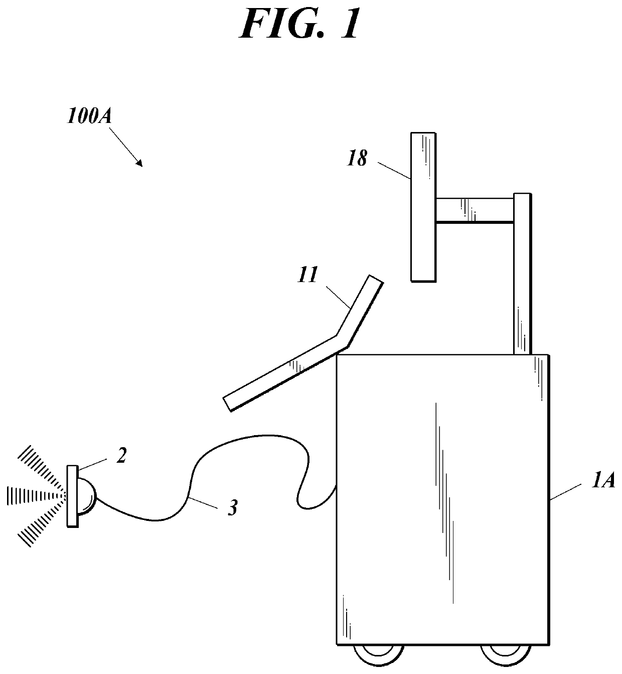
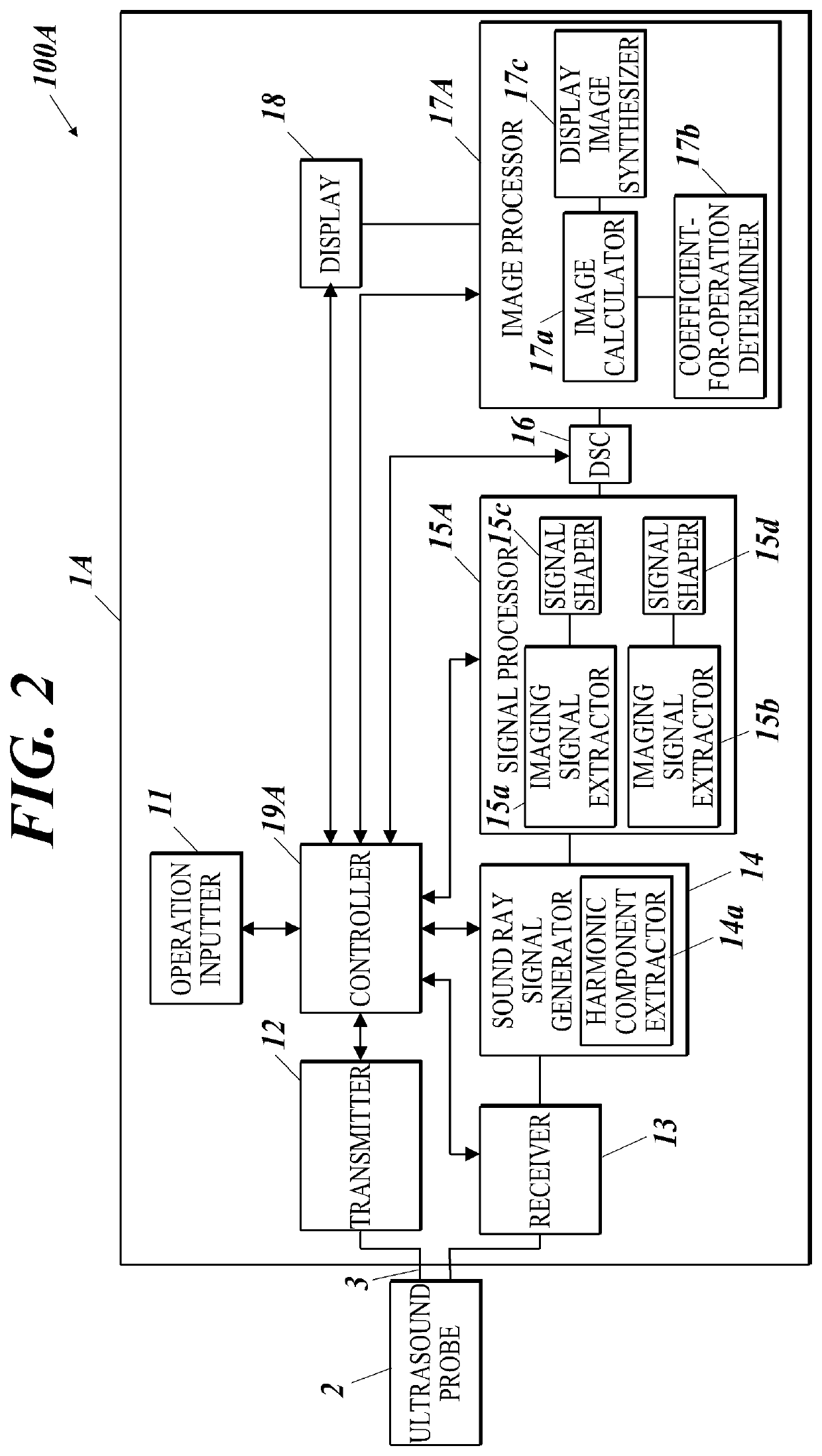
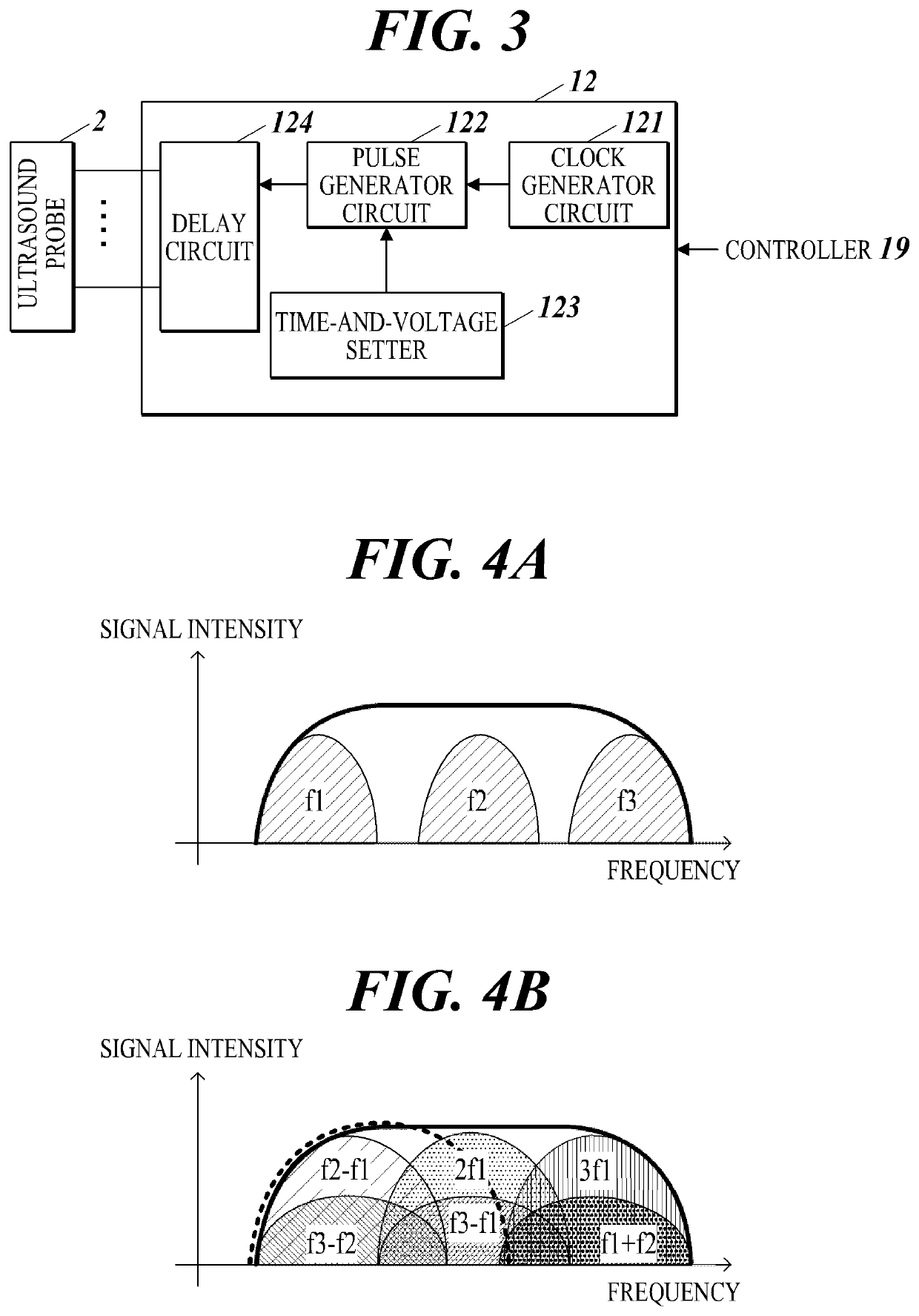
[0033]The first embodiment of the present disclosure will be described with reference to FIG. 1 to FIG. 9. First, with reference to FIG. 1 to FIG. 8, the configuration of a diagnostic ultrasound apparatus 100A as a diagnostic ultrasound apparatus of this embodiment will be described. FIG. 1 shows the external configuration of the diagnostic ultrasound apparatus 100A according to this embodiment. FIG. 2 is a block diagram showing the functional configuration of the diagnostic ultrasound apparatus 100A. FIG. 3 is a block diagram showing the functional configuration of a transmitter 12. FIG. 4A shows frequency characteristics of signal intensity of transmission ultrasound. FIG. 4B shows frequency characteristics of signal intensity of reflected ultrasound.

[0034]FIG. 5 shows that an ultrasound image F2 is subtracted from an ultrasound image F1, so that a difference image F3 is generated, and that the difference image F3 is subtracted from the ultrasound image F1, so that a sub-differenc...

example

[0085]Next, as an example of the first embodiment, observation examples will be described in which the diagnostic ultrasound apparatus 100A was used to scan phantoms as the subject, and analysis information thereon was obtained. Phantoms P1 to P4 were prepared as phantoms to be observed (i.e. observation target(s)). The composition (characteristics) of each of the phantoms P1 to P4 is summarized in Table I below.

TABLE ICOMPOSITION OF PHANTOMPHANTOMMAINREFLECTIONSCATTERSCATTERNO.MATERIALSUBSTANCE ASUBSTANCE BSUBSTANCE CWIRE TARGETP1AGAR———DEPTH 15 mmP2100——EMBEDDEDP310030—P41003030

[0086]Each of the phantoms P1 to P4 was composed of a main material of agar as a base, a wire target as a wire to be observed (observation target) embedded in the agar, and a reflection substance A and scatter substances B. C arbitrarily mixed. The reflection substance A was polystyrene beads having a mean particle diameter of 600 μm, and a material manufactured by Polysciences Inc, was used. The scatter su...

second embodiment

[0117]A second embodiment of the present disclosure will be described with reference to FIG. 10 and FIG. 11. FIG. 10 is a block diagram showing the functional configuration of a diagnostic ultrasound apparatus 100B according to this embodiment. FIG. 11 is a flowchart showing a second-ultrasound-image display process.

[0118]In the first embodiment, the first and second image data are generated from the first and second imaging signals, and the sub-difference image data is generated from the first and second image data. However, in tins embodiment, a sub-difference imaging signal is generated from the first and second imaging signals, and the sub-difference image data is generated therefrom.

[0119]The apparatus configuration of this embodiment will be described with reference to FIG. 10. In this embodiment, the diagnostic ultrasound apparatus 100B is used. Components of the diagnostic ultrasound apparatus 100B different from those of the diagnostic ultrasound apparatus 100A of the first...


PUM


Abstract

A diagnostic ultrasound apparatus includes a sound ray signal generator, an extractor and an arithmetic unit. The sound ray signal generator generates a sound ray signal based on a reception signal obtained from an ultrasound probe. The ultrasound probe transmits and receives ultrasound to and from a subject. The extractor extracts imaging signals from the sound ray signal by performing filtering of passing different bands. The arithmetic unit generates a difference signal by using the imaging signals, and performs an arithmetic operation on at least one of the imaging signals by using the difference signal.

Description

CROSS-REFERENCE TO RELATED APPLICATIONS[0001]The entire disclosure of Japanese Patent Application No. 2020-039480 filed on Mar. 9, 2020 is incorporated herein by reference in its entirety.BACKGROUNDTechnological Field[0002]The present disclosure relates to a diagnostic ultrasound apparatus and a computer readable storage medium.Description of the Related Art[0003]An ultrasound (ultrasonography) can be performed repeatedly because it produces an ultrasound image showing the state of a heart or a fetus by a simple operation of applying an ultrasound probe to the body surface or the body cavity of a subject of a patient and has high safety. A diagnostic ultrasound apparatus used for such ultrasounds is known.[0004]An ultrasound image usually displays echo signal components of reflected ultrasound (echo) obtained by ultrasound being reflected by structures larger than the ultrasound wavelength and echo signal components obtained by ultrasound being scattered by structures smaller than t...

Claims


Application Information

Patent Timeline
IPC IPC(8): A61B8/08
CPCA61B8/5223A61B8/08A61B8/5246A61B8/4405A61B8/5207A61B8/54G01S15/8954G01S15/8977G01S7/52047
Inventor TANIGUCHI, TETSUYA
Owner KONICA MINOLTA INC
Why Eureka
Try Eureka