
Stylus

A stylus and capacitive touch technology, applied in the direction of instruments, electrical digital data processing, input/output process of data processing, etc.

Inactive Publication Date: 2016-01-27
PRIMAX ELECTRONICS LTD
View PDF6 Cites 11 Cited by
  • Summary
  • Abstract
  • Description
  • Claims
  • Application Information

AI Technical Summary

Problems solved by technology

[0004] However, the existing capacitive stylus can only interact with the capacitive touch panel to perform functions such as writing, drawing, and selecting. How to improve the functionality of the capacitive stylus in today's highly popularized capacitive stylus , so that it can be used not only for capacitive touch panels, but also for other electronic devices is an important issue

Method used


Image

  • Stylus
  • Stylus
  • Stylus

Examples


Embodiment Construction

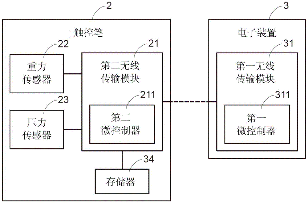
[0036] A stylus 2 is provided according to a preferred embodiment of the present invention, please refer to figure 2 and image 3 , figure 2 is a cross-sectional view of a stylus in a preferred embodiment of the present invention, image 3 It is a block diagram of a stylus and an electronic device according to a preferred embodiment of the present invention.

[0037] First, the elements of the stylus 2 will be described. The stylus 2 of this example includes a pen head 20 and a second wireless transmission module 21 disposed on a circuit board 24, a gravity sensor 22 (G-Sensor), a pressure sensor 23, a laser light source 25, two push keys 26, and an indicator light source 29 and memory 34 . The second wireless transmission module 21 includes a second micro-controller 211 (MCU), the laser light source 25 is set toward the pen tip 20 , and the pen tip 20 includes a hole 201 for passing the light emitted by the laser light source 25 . The stylus 2 of this example is a pass...


PUM


Abstract

The invention relates to a stylus which is used for operating a capacitive touch panel and an electronic device, wherein the electronic device is provided with a first wireless transmission module. The stylus comprises a nib, a second wireless transmission module, a weight sensor and a pressure sensor, wherein the nib is used for interacting with the capacitive touch panel; the second wireless transmission module is used for communicating with the first wireless transmission module; according to the angle change of the stylus, sensed by the weight sensor, the second wireless transmission module transmits a corresponding first control signal to the first wireless transmission module to control the electronic device; and according to the pressure borne by the nib, sensed by the pressure sensor, the second wireless transmission module transmits a corresponding second control signal to the first wireless transmission module or the capacitive touch panel to control the electronic device or the capacitive touch panel. The stylus provided by the invention can be used for operating the capacitive touch panel and the electronic device, so that a complex function is provided.

Description

technical field [0001] The present invention relates to a stylus, in particular to a stylus for manipulating capacitive touch panels and electronic devices. Background technique [0002] Common touch panels on the market can be classified into resistive, acoustic, infrared and capacitive types. The resistive touch panel recognizes commands by the voltage generated by external pressure. The surface of the acoustic wave or infrared touch panel is covered with acoustic waves or infrared rays, and the identification method is to block the transmission of the acoustic waves or infrared rays by contact. The capacitive touch panel uses the change of the capacitance value of the touch panel at the contact point when the human body touches the touch panel to determine the touch position. Based on considerations of touch accuracy and cost, capacitive touch panels are currently widely used. [0003] Therefore, in response to the functionality of the capacitive touch panel, a capacit...

Claims


Application Information

Patent Timeline
Patent Type & Authority Applications(China)
IPC IPC(8): G06F3/0354G06F3/038
CPCG06F3/017G06F3/0346G06F3/03545G06F3/0441G06F3/0442
Inventor 蓝世杰曾英哲张阿明
Owner PRIMAX ELECTRONICS LTD
Learn More