
Directly generate linearly polarized te 11 relativistic return wave tube

A relativistic return wave tube, TE11 technology, applied in the field of masers, can solve the problems of complex structure, difficult processing, low interaction efficiency, etc., achieve high conversion efficiency, simple structure, and improve beam conversion efficiency

Active Publication Date: 2017-04-26
NORTHWEST INST OF NUCLEAR TECH
View PDF6 Cites 0 Cited by
  • Summary
  • Abstract
  • Description
  • Claims
  • Application Information

AI Technical Summary

Problems solved by technology

However, the structure of the Bragg reflector used is complex and difficult to process; in order to ensure sufficient mode conversion, the Bragg reflector must have multiple periods, and its length is equivalent to or even longer than that of the slow wave structure, resulting in the overall failure of the magnetic field coil and the return wave tube. lengthened; in addition, the Bragg reflector affects the modulation of the electron beam, resulting in the TM in the electron beam and the slow wave structure 01 Mode interaction efficiency is low, only 16.5%

Method used


Image

  • Directly generate linearly polarized te  <sub>11</sub> relativistic return wave tube
  • Directly generate linearly polarized te  <sub>11</sub> relativistic return wave tube
  • Directly generate linearly polarized te  <sub>11</sub> relativistic return wave tube

Examples


Embodiment Construction

[0029] In order to better understand the present invention, the linearly polarized TE of the present invention is directly produced below in conjunction with the accompanying drawings and examples 11 The relativistic return wave tube of the mode is described in detail.

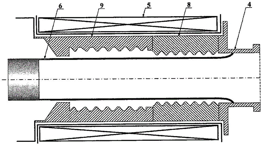
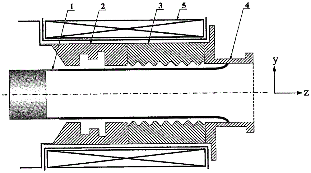
[0030] image 3 , 4 A schematic diagram of an embodiment of the present invention is given. image 3 The electron beam output direction along the central axis of the relativistic return wave tube is the z axis, the vertical z axis is the y axis, and the vertical y and z axes point to the paper surface is the x axis. image 3 is the structural representation on the yz section of this embodiment, Figure 4 It is a structural schematic diagram on the xz section of this embodiment. The relativistic return wave tube provided by the present invention includes an arc cathode 1 , a double pre-modulated cavity 2 , an angularly partitioned slow wave structure 3 , an output waveguide 4 and a magnetic field coil 5 . ...


PUM


Abstract

The invention, which belongs to the maser field, directly relates to a relativistic backward wave oscillator for generating a linearly polarized TE11 mode directly. The relativistic backward wave oscillator comprises an arc cathode, a reflector, an angular partition slow wave structure, an output waveguide and a magnetic field coil. The arc cathode is arranged at the front end of the relativistic backward wave oscillator; the reflector, the angular partition slow wave structure, and the output waveguide are arranged at the rear side of the arc cathode successively; and the magnetic field coil is installed at the periphery. According to the invention, with the nonaxisymmetrical arc cathode and the angular partition slow wave structure, the TE11 mode is excited directly. The reflector employs the dual-premodulation-cavity unit preferably and is used for carrying out premodulation on an arc relativistic electron beam and leaking the part of TE11 mode to enter the arc cathode zone, so that certain premodulation of the electron beam at the arc cathode zone is realized and thus the beam wave conversion efficiency is improved. Moreover, the oscillator has advantages of simple structure and high conversion efficiency; and the linearly polarized TE11 mode can be generated directly.

Description

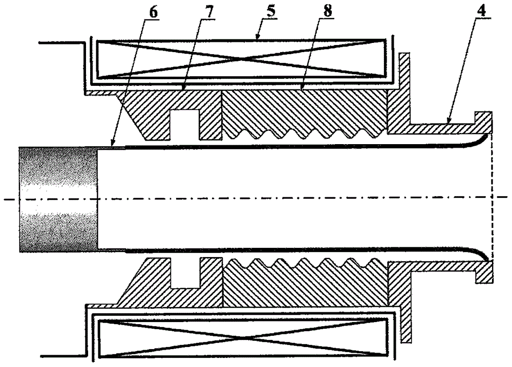
technical field [0001] The invention belongs to the field of microwave masers, in particular to a relativistic return wave tube. Background technique [0002] The relativistic backward wave oscillator (hereinafter referred to as RBWO) has the characteristics of high power, high efficiency, and suitable for repetition frequency operation, and is one of the most important high-power microwave sources. Currently commonly used RBWO such as figure 1 As shown (patent number: ZL200710082042.4, high power relativistic return wave tube), it includes a ring cathode 6, a resonant reflector 7, a slow wave structure 8, an output waveguide 4 and a magnetic field coil 5. The ring cathode 1 is located at the front of the device, the resonant reflector 7, the slow wave structure 8 and the output waveguide 4 are separated from the ring cathode 6 by a certain distance, and placed behind it in turn, and the magnetic field coil 5 is located at the ring cathode 6, the resonant reflector 7 and th...

Claims


Application Information

Patent Timeline
Patent Type & Authority Patents(China)
IPC IPC(8): H01J23/04H01J23/24H01J25/00
Inventor 肖仁珍张余川李佳伟宋志敏孙钧
Owner NORTHWEST INST OF NUCLEAR TECH
Learn More