
Working method of switch cabinet for electric power system

A working method and switchgear technology, applied in the field of electric power engineering, can solve problems such as inability to drive instruments, instrument work, display, setting functions, and electrical instruments cannot supply power normally, so as to achieve a variety of voltage output types and save calculation time , the effect of prolonging life

Inactive Publication Date: 2016-01-27
朱海燕
View PDF1 Cites 1 Cited by
  • Summary
  • Abstract
  • Description
  • Claims
  • Application Information

AI Technical Summary

Problems solved by technology

[0002] In the power system, a large number of ring network cabinets are used in the power supply system, but there is no AC / 220V power supply in the ring network cabinet, causing many electrical instruments to fail to supply power normally, and most of them use CT (Current Transformer, current transformer) to take power as power supply , and once the primary current is too small, the CT coil cannot supply power to the instrument normally, so that the instrument cannot work normally, and even the display and setting functions cannot be used, which will bring unnecessary troubles to operation and maintenance; it will not be able to drive related instruments , Instrument work, such as: cable head temperature online monitoring device and ring network cabinet anti-misoperation locking device

Method used


Image

  • Working method of switch cabinet for electric power system
  • Working method of switch cabinet for electric power system
  • Working method of switch cabinet for electric power system

Examples


Embodiment 1

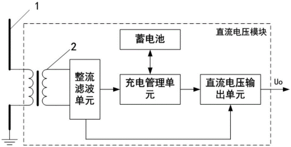
[0034] see figure 1 , A switch cabinet, comprising a DC voltage module suitable for generating a DC voltage output, the DC voltage module taking power from the bus 1 end of the switch cabinet.

[0035] The DC voltage module can supply power to the ring main unit anti-misoperation locking device and the cable head temperature online monitoring device; the ring main unit anti-misoperation locking device adopts the utility model patent "Ring main unit anti-misoperation locking device" authorized Announcement number CN202196675.

[0036] The DC voltage module generates 24V or 28V or 220V DC voltage, and can also control the DC voltage output according to the user.

Embodiment 2

[0038] The implementation of the DC voltage module on the basis of embodiment 1 is as follows:

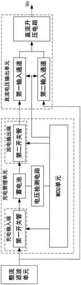
[0039] see figure 2 , The DC voltage module includes: a transformer 2 adapted to take power from the bus 1 end of the switch cabinet, the transformer 2 is connected to a rectifying filter unit, and a charging management unit suitable for controlling the charge / discharge of the battery , DC voltage output unit;

[0040] Wherein, the charging management unit includes: a voltage detection unit, an MCU unit, a charging input end provided with a first switch tube, the charging input end is connected to the output end of the rectification filter unit, and a discharge output provided with a second switching tube end;

[0041] The DC voltage output unit includes: a first input channel connected to the discharge output terminal, and the first input channel is adapted to receive the battery DC voltage output by the charging management unit; A second input channel; the first and second input chan...


PUM


Abstract

The invention relates to a working method of a switch cabinet for an electric power system. The switch cabinet comprises a direct current voltage module which is suitable for producing direct current voltage output, and the direct current voltage module takes power from a bus bar end of the switch cabinet. The direct current voltage module comprises a mutual inductor, a charging management unit and a direct current voltage output unit, wherein the mutual inductor is suitable for taking power from the bus bar end of the switch cabinet and is connected with a rectifier filter unit; the charging management unit is suitable for controlling charging and discharging of a storage battery. According to the working method of the switch cabinet for the electric power system, the direct current voltage module which is arranged inside provides corresponding direct current voltage so as to meet normal work of relevant instruments and meters in the switch cabinet; an MCU unit is used for controlling charging and discharging, an over charging phenomenon of the storage battery is avoided, the service life of the storage battery is prolonged effectively, power required for normal work of the instruments and meters during power failure maintenance is provided by the storage battery, and a power supply is not required to be connected externally.

Description

Technical field [0001] The invention belongs to the technical field of electric power engineering, and in particular relates to a switch cabinet with a built-in power supply module and a working method thereof. Background technique [0002] In the power system, a large number of ring network cabinets are used in the power supply system, but there is no AC / 220V power supply in the ring network cabinet, causing many electrical instruments to be unable to supply power normally. Most of them use CT (Current Transformer, current transformer) as the power supply. , And once the primary current is too small, the CT power coil cannot supply power to the instrument normally, making the instrument unable to work normally, and even the display and setting functions cannot be used, which brings unnecessary troubles to operation and maintenance; it is also unable to drive related instruments. , The work of the instrument, such as: cable head temperature online monitoring device and ring netwo...

Claims


Application Information

Patent Timeline
Patent Type & Authority Applications(China)
IPC IPC(8): H02J7/00
CPCH02B1/24H02J5/005H02J7/022H02J7/027H02J7/34H02J9/062H02J11/00H02M1/10H02M7/48Y02E60/10
Inventor 不公告发明人
Owner 朱海燕
Features
  • Generate Ideas
  • Intellectual Property
  • Life Sciences
  • Materials
  • Tech Scout
  • Unparalleled Data Quality
  • Higher Quality Content
  • 60% Fewer Hallucinations
Learn More