
rf receiver

A receiver, transfer function technology, applied in electrical components, transmission systems, etc., can solve problems such as hindering the baseband demodulator, failure, and inability to correct, and achieve the effect of maximizing RF performance

Inactive Publication Date: 2018-06-29
NXP BV
View PDF5 Cites 0 Cited by
  • Summary
  • Abstract
  • Description
  • Claims
  • Application Information

AI Technical Summary

Problems solved by technology

[0007] Although this method is able to optimize the performance of the receiver under static conditions, it fails when the communication channel has dynamic characteristics
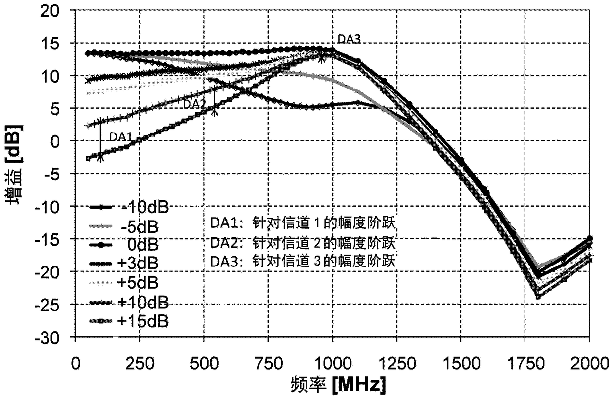
This is because the reconfiguration of the RSPU (and specifically the RF filter) causes a transient amplitude step that hampers the baseband demodulator and causes uncorrectable errors in transmission, especially for higher order modulations (e.g. 256QAM and above)

Method used


Image

  • rf receiver
  • rf receiver
  • rf receiver

Examples


Embodiment Construction

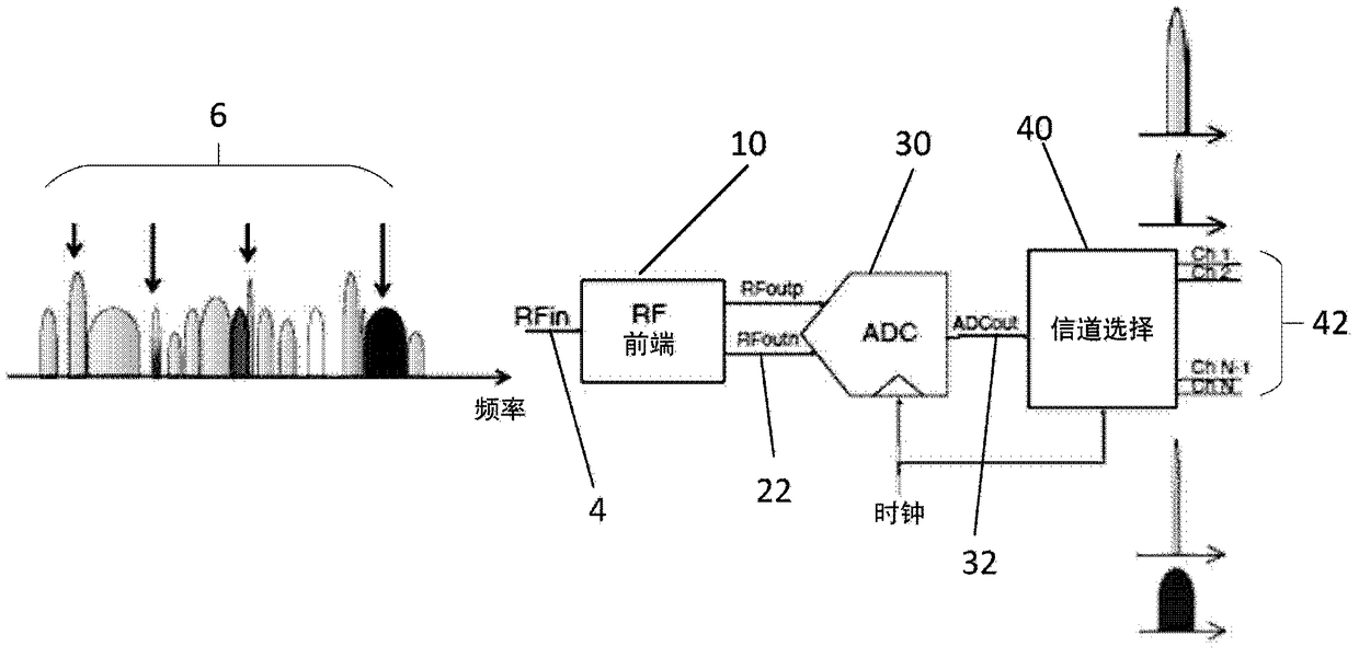
[0050] Figure 4An RF receiver 2 in the form of a direct RF digitizing receiver 2 according to an embodiment of the invention is shown. The receiver 2 comprises an RF signal processing unit (RSPU) 10 for receiving RF signals. RSPU 10 includes a low noise amplifier 12, a dynamically reconfigurable RF filter 14 for filtering the RF signal output by the low noise amplifier 12, and other analog components 16 for processing the signal output by the RF filter 14 (typically , low-noise amplifier, low-pass filter, and single-difference amplifier). RSPU 10 also includes an I2C communication bus for communicating with a main processor 20 , which may be in the form of a system-on-chip 20 .

[0051] The RF receiver 2 also includes an analog-to-digital converter (ADC) 30 and a digital signal processing unit (DSPU) 40 for converting the filtered RF signal 22 output by the RSPU 10 into a digital signal 32, the digital The signal processing unit is used to process the digital signal output...


PUM


Abstract

An RF receiver (2) comprising: an RF signal processing unit (10) for receiving an RF signal (4), wherein the RF signal processing unit (10) comprises a dynamically reconfigurable filter for the RF signal (4) RF filter (14); analog-to-digital converter (30) for converting the filtered RF signal (22) to a digital signal (32); and processing the digital signal (32) to provide at least one channel (42) ); wherein the digital signal processing unit (40) is adapted to adjust the corresponding transfer function of at least one of said channels (42) upon reconfiguration of the RF filter (14) to at least partially compensate Variation in the transfer function of the RF filter (14).

Description

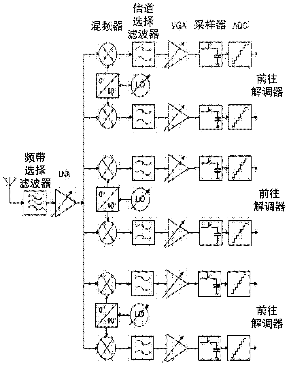
technical field [0001] The present invention relates to RF receivers, and in particular but not exclusively to RF receivers having dynamically reconfigurable RF signal processing units. Background technique [0002] Communication systems that handle high data rates often require the use of multiple parallel receivers or a single wideband receiver. [0003] figure 1 A bank of single-channel receivers is shown, comprising a plurality of single-channel receivers for each respective channel to be simultaneously received. This approach results in high cost and high power consumption. [0004] Once the useful part of the spectrum occupies a moderate part of the entire input spectrum, it is different from the traditional method using multiple single-channel receivers ( figure 1 ) compared to using a single direct RF digitizing receiver ( figure 2 ) have been shown to be more efficient in terms of power and cost. [0005] figure 2 A direct RF digitizing receiver is shown, co...

Claims


Application Information

Patent Timeline
Patent Type & Authority Patents(China)
IPC IPC(8): H04B1/16
CPCH04B1/001H04B1/0014H04B1/0017H04B1/1018
Inventor 奥利弗·贾明法比安·勒菲弗吉尔斯·塞弗里安
Owner NXP BV
Learn More