Hydrodynamic focusing apparatus and methods

A fluid focusing, fluid technology, applied in chemical instruments and methods, mechanical equipment, transportation and packaging, etc., can solve difficult manufacturing, complex design and other problems

Active Publication Date: 2016-01-27
CYTONOMEST
View PDF29 Cites 11 Cited by
  • Summary
  • Abstract
  • Description
  • Claims
  • Application Information

AI Technical Summary

Problems solved by technology

[0007] Conventional devices that have been applied to achieve sheath flow have relatively complex designs and are relatively difficult to manufacture

Method used


Image

  • Hydrodynamic focusing apparatus and methods
  • Hydrodynamic focusing apparatus and methods
  • Hydrodynamic focusing apparatus and methods

Examples


Embodiment Construction

[0048] According to some embodiments, a microfluidic particle (e.g., cell) analysis and / or sorting system for a microfluidic chip as a therapeutic enabling cell-based therapy (such as blood transfusion, bone marrow transplantation, and / or mobilization of peripheral blood transplantation, etc.) Medical devices may have a wide variety of applications. Embodiments of the microfluidic sorting system may be able to select cells based on intrinsic properties determined by the interaction of light with cells (eg, scattering, reflection, and / or autofluorescence) independent of the protocol and necessary reagents. The microfluidic system may employ a closed, sterile, disposable cartridge containing the microfluidic chip. Microfluidic systems can handle high-velocity particles (eg, cells) and deliver particles (eg, cells) with high yield and purity.

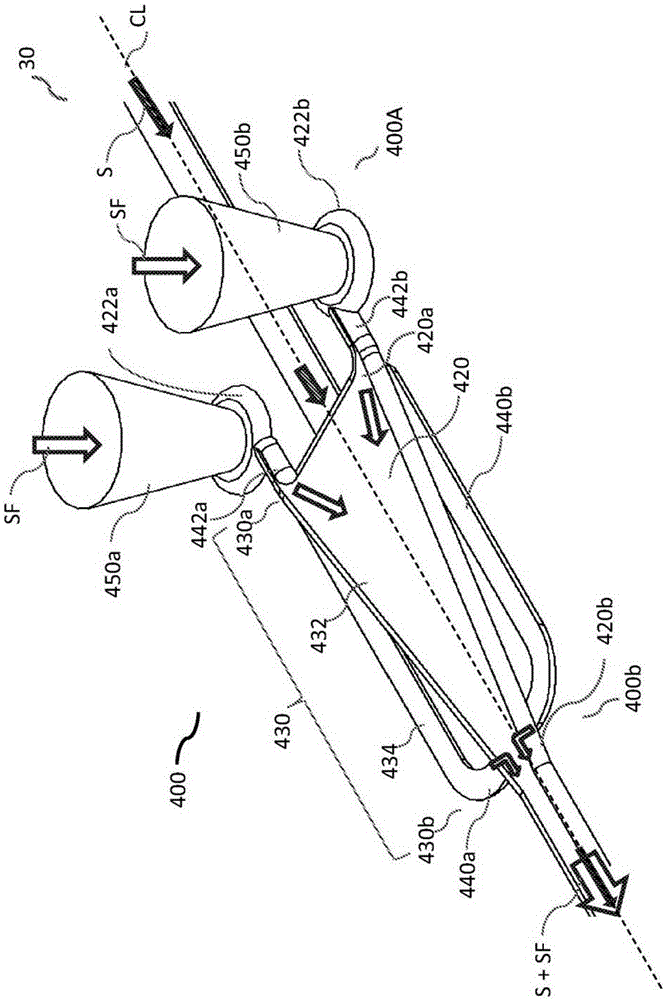
[0049] Certain embodiments described herein relate to systems and methods for generating sheath flow in flow channels, and in particular...


PUM

PropertyMeasurementUnit
thicknessaaaaaaaaaa
thicknessaaaaaaaaaa
thicknessaaaaaaaaaa

Abstract

A microfluidic chip having a micro channel for processing a sample is provided. The micro channel may focus the sample by using focusing fluid and a core stream forming geometry. The core stream forming geometry may include a lateral fluid focusing component and one or more vertical fluid focusing components. A microfluidic chip may include a plurality micro channels operating in parallel on a microfluidic chip.

Description

[0001] related application [0002] This application claims priority to US Provisional Application 61 / 785,734, filed March 14, 2013, entitled "Hydrodynamic Focusing Apparatus and Methods," the entire contents of which are hereby incorporated by reference. technical field [0003] The present invention relates generally to hydrodynamic focusing, and more particularly to microfluidic devices. More specifically, the present invention relates to systems and methods for generating sheath flow in flow channels, and in particular microchannels in microfluidic devices. Background technique [0004] Sheath flow is a special type of laminar flow in which a layer of focusing fluid surrounds particles or another layer of sample fluid particles on more than one side. The process of confining a particle stream within a fluid is known as a "sheath flow" configuration. For example, in a sheath flow configuration, a sheath fluid can envelop and pinch a sample fluid containing a plurality o...

Claims


Application Information

Patent Timeline
Patent Type & Authority Applications(China)
IPC IPC(8): G01N15/14
CPCG01N2015/1409G01N2015/1411G01N2015/1413G01N15/1404Y10T137/8359Y10T137/2076G01N2203/0264B01L3/502776B01L2200/0636F16K2099/008B01F33/3011F17D1/08F17D5/00
Inventor J·C·夏普E·库科萨尔K·S·布坎南B·D·莫拉达
Owner CYTONOMEST
Why Eureka
Try Eureka