An electric mosquito swatter with a plug and a control switch
A technology for controlling switches and plug strips, which can be used in devices for catching or killing insects, applications, animal husbandry, etc. It can solve problems such as accidents and dangers, and achieve the effects of avoiding electric shock, quick assembly, and simple structure
- Summary
- Abstract
- Description
- Claims
- Application Information
AI Technical Summary
Problems solved by technology
Method used
Image
Examples
no. 1 example
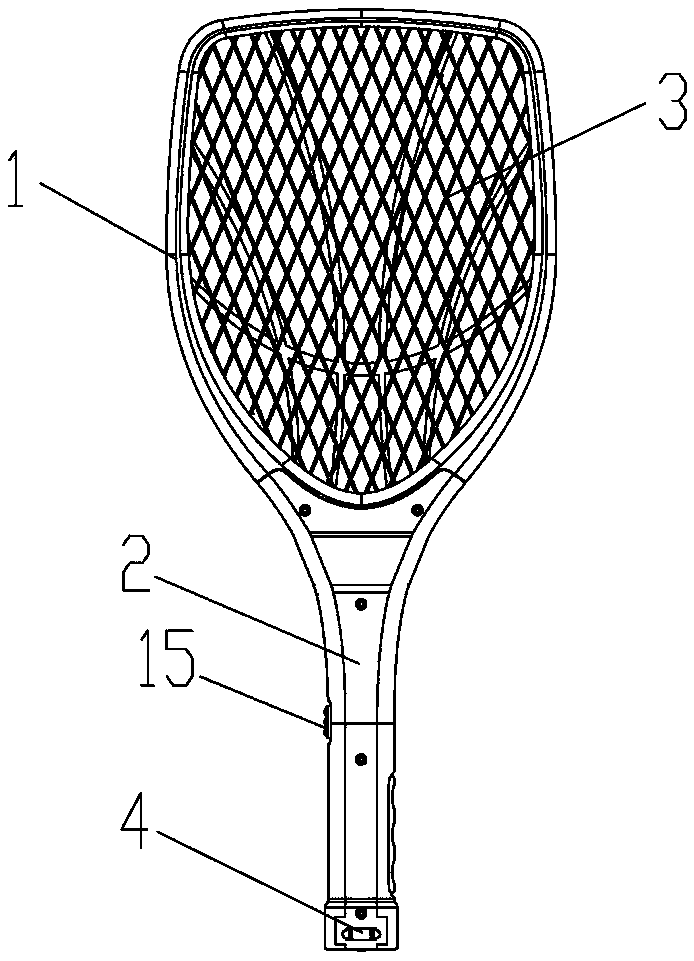
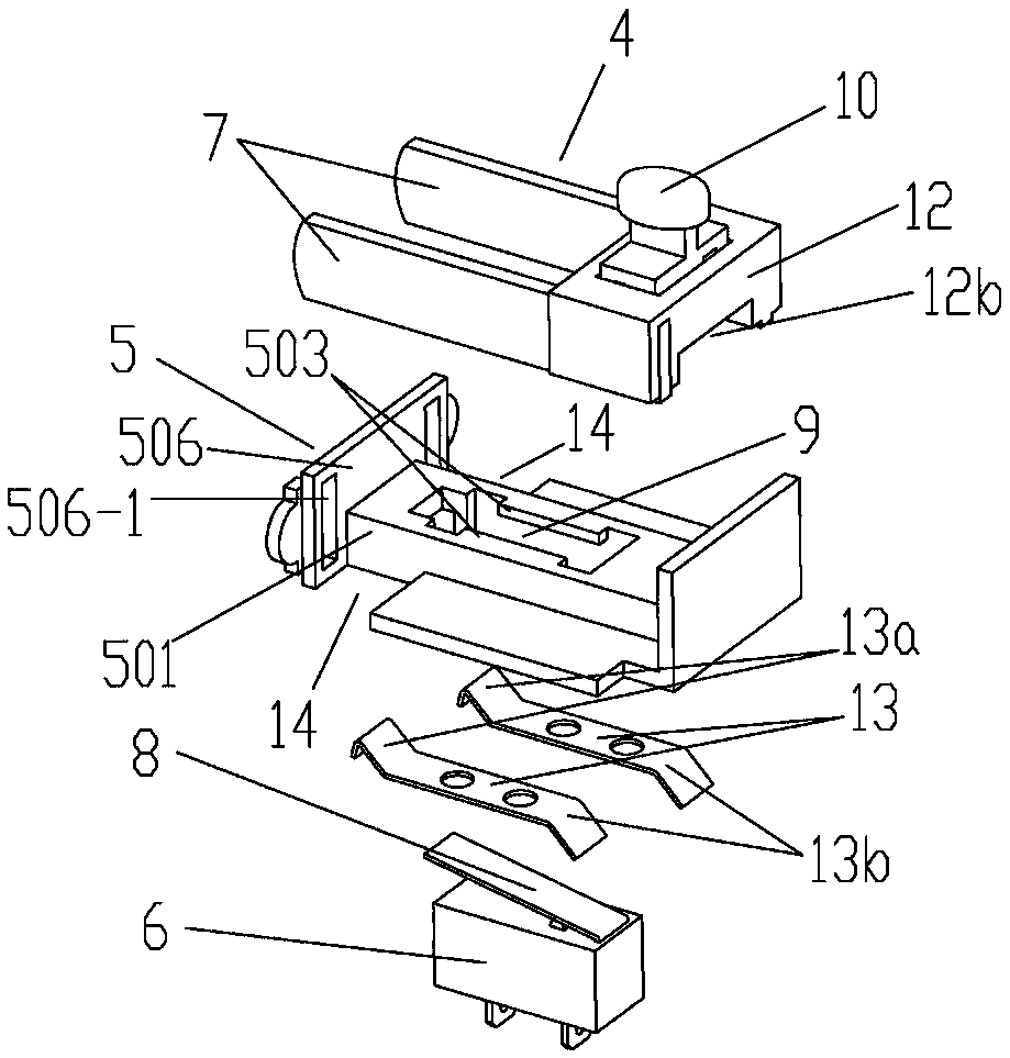
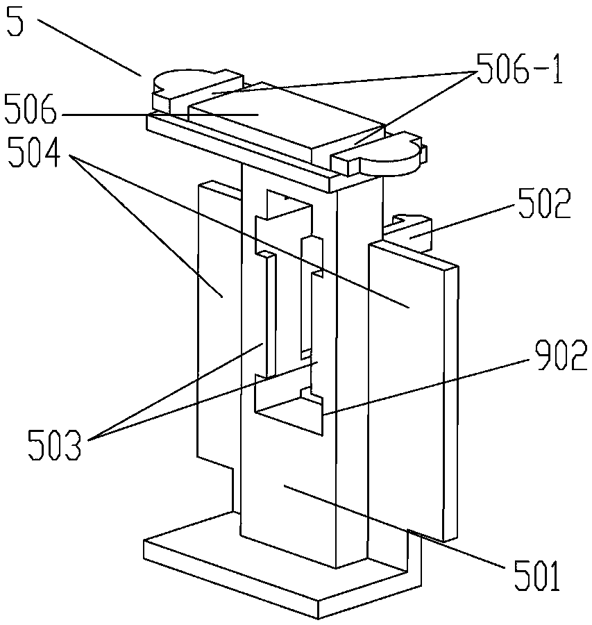
[0026] The first embodiment: as Figure 1 to Figure 7 As shown, an electric mosquito swatter with a plug and a control switch includes a racket body 1 and a handle 2, an electric shock net 3 is installed on the racket body 1, and a hidden movable plug 4 is installed at the bottom of the handle 2. It is characterized in that: A support seat 5 is fixed inside the handle 2, and the hidden movable plug 4 is slidably connected to the support seat 5. A control switch 6 connected to the electric shock net 3 is installed on the support seat 5. When the hidden movable plug extends out of the handle 2, when the control switch is disconnected, the electric shock net 3 is powered off. When the electric mosquito swatter of this structure is charging, the hidden movable plug 4 extends out of the handle 2, and the electric shock net 3 is powered off, without the risk of high voltage output, which is safer and more reliable, even if someone forgets to turn off the switch 15 and touches the el...
no. 2 example
[0035] The second embodiment: as Figure 8 As shown in the convex 9, it is similar to the first embodiment, the difference is that the control switch 6 uses a bipolar micro switch (as can be seen from the connecting pin at the bottom of the switch), and the bipolar micro switch simultaneously turns on the circuit When the live wire and the neutral wire of the control switch 6 are pressed against the recess 12b and the lever 8 of the control switch 6 is pressed down, the live wire and the neutral wire connected to the control switch 6 are disconnected simultaneously, which conforms to the standard of the International Electrotechnical Commission IEC.
no. 3 example
[0036] The third embodiment: as Figure 10 As shown, similar to the second embodiment, the difference is that the control switch 6 uses two unipolar micro switches, which are respectively connected to the live wire and the neutral wire of the circuit through the two unipolar micro switches, which can also achieve simultaneous The purpose of disconnecting the bipolar; in addition, since two unipolar micro switches are provided, the size of the mounting hole 9 needs to be increased accordingly, since this is easily realized by those skilled in the art, it will not be described in detail here.
[0037] In the above embodiment, the control switch 6 can be adjusted to a normally open micro switch, and through the adjustment of the circuit wiring, the function of powering off the electric shock net 3 can also be realized when the battery is charging.
[0038] The pick bar 8 can also be called a seesaw, but its effect and function are the same.
PUM
 Abstract
Description
Claims
Application Information
 - R&D
- Intellectual Property
- Life Sciences
- Materials
- Tech Scout
- Unparalleled Data Quality
- Higher Quality Content
- 60% Fewer Hallucinations
Browse by: Latest US Patents, China's latest patents, Technical Efficacy Thesaurus, Application Domain, Technology Topic, Popular Technical Reports.
© 2025 PatSnap. All rights reserved.Legal|Privacy policy|Modern Slavery Act Transparency Statement|Sitemap|About US| Contact US: help@patsnap.com


