Combined ectosteal reduction device

A combination and slider technology, applied in the field of medical equipment, can solve the problems of poor bone setting effect, inaccurate alignment line, lack of standardization, etc., and achieve the advantages of simple and easy to use, small and light size, and improved scientificity Effect

Inactive Publication Date: 2016-02-03
HARBIN BOSI SHOUCHUANG MEDICAL DEVICE
View PDF9 Cites 12 Cited by
  • Summary
  • Abstract
  • Description
  • Claims
  • Application Information

AI Technical Summary

Problems solved by technology

[0004] The purpose of the present invention is to solve the problem that the existing long bone fractures of the extremities are manually sorted out, which is labor-intensive, takes a long time to sort out, and the alignment line is i

Method used


Image

  • Combined ectosteal reduction device
  • Combined ectosteal reduction device
  • Combined ectosteal reduction device

Examples


specific Embodiment approach 1

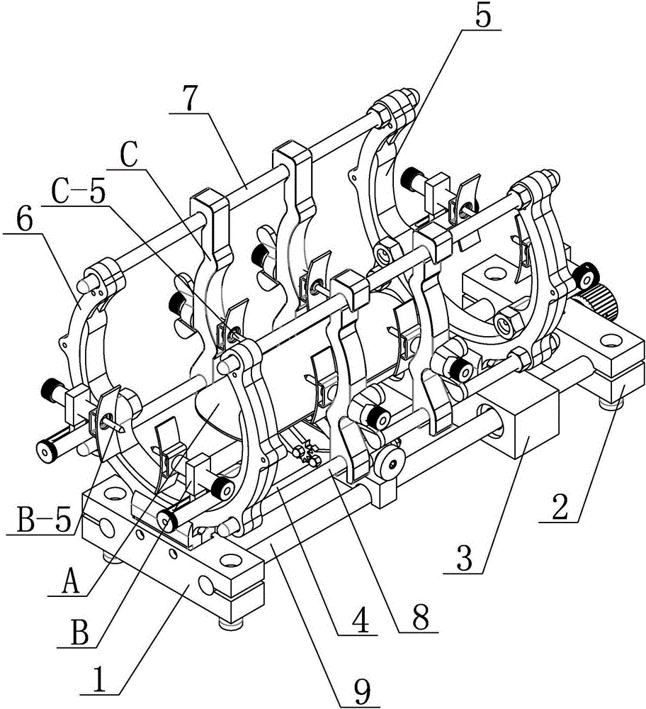
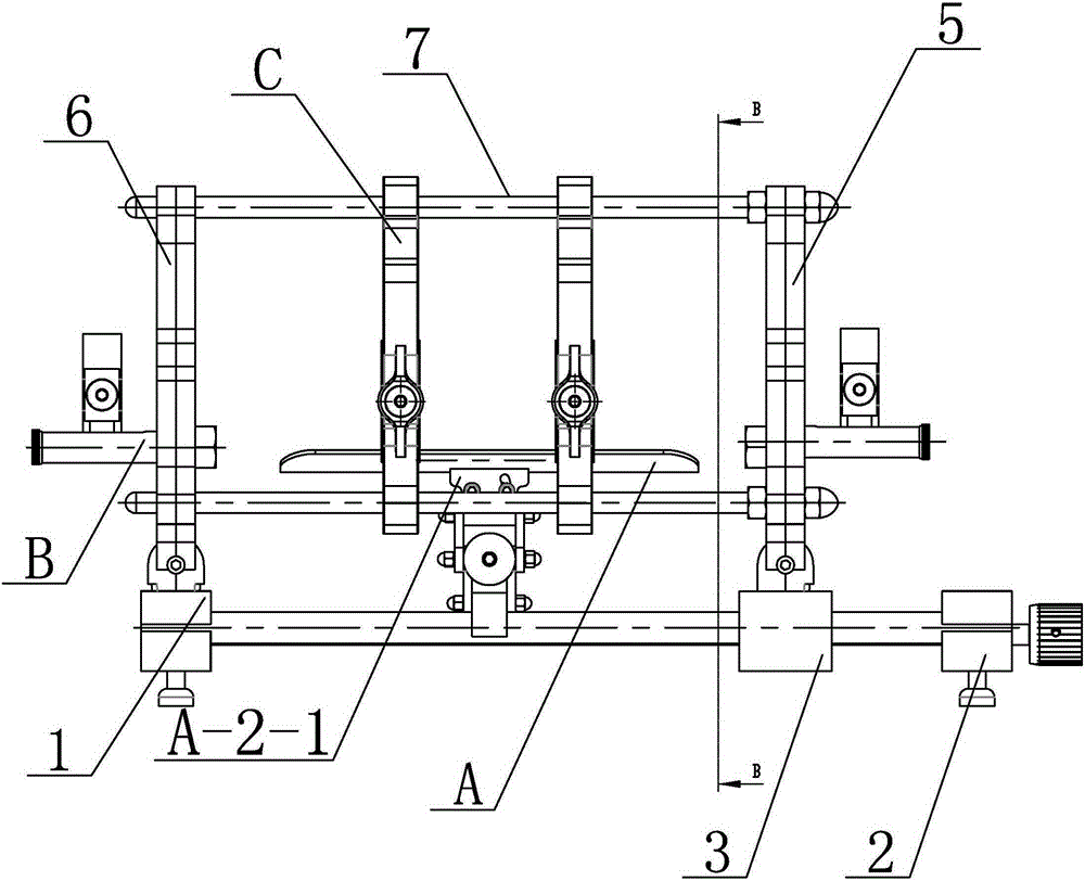
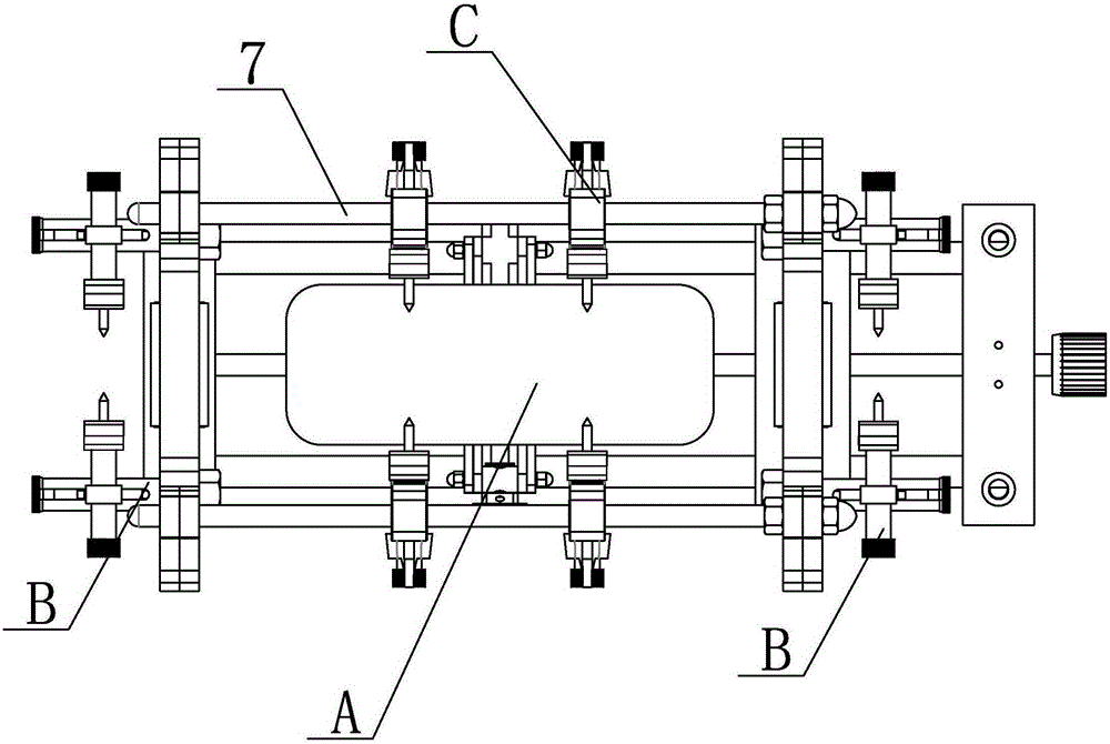
[0021] Specific implementation mode one: combine Figure 1 to Figure 15 Describe this embodiment, a combined extraosseous reduction device of this embodiment, which includes a half-ring reduction device, and the half-ring reduction device includes a first fixed slider 1, a second fixed slider 2, a moving Slider 3, lead screw 4, first rotating ring 5, second rotating ring 6, two upper sliding rods 7, two lower rods 8 and multiple moving rods 9, first fixed slider 1 and second fixed slider 2 Arranged sequentially from left to right, the moving slider 3 is arranged between the first fixed slider 1 and the second fixed slider 2, and a plurality of moving rods 9 can slide through the first fixed slider 1 and the second fixed slider in turn. On the fixed slider 2 and the movable slider 3, one end of the screw 4 passes through the second fixed slider 2, the movable slider 3 and the first fixed slider 1 in turn, and the other end of the screw 4 extends to the second fixed slider The ...

specific Embodiment approach 2

[0022] Specific implementation mode two: combination Figure 1 to Figure 6 , Figure 10 to Figure 12 To illustrate this embodiment, the lifting pallet A of this embodiment includes a pallet body A-1, a pallet ear plate A-2, a lifting frame and a lower connection seat A-3, and the pallet body A-1 is rotatably mounted on the pallet ear plate A -2, the lower end of the tray ear plate A-2 is connected with the upper end of the lifting frame, and the lower end of the lifting frame is connected with the lower connection seat A-3. With such a setting, it is convenient to flexibly adjust the placement angle of the patient's fracture site, that is, the upward angle is 20° and the downward angle is 20°. Other compositions and connections are the same as in the first embodiment.

specific Embodiment approach 3

[0023] Specific implementation mode three: combination Figure 1 to Figure 6 , Figure 10 to Figure 12 This embodiment will be described, the pallet body A-1 of the present embodiment is an arc-shaped pallet. With such setting, the fracture site of the patient is provided with all-round angle support. Other compositions and connections are the same as those in the second embodiment.


PUM


Abstract

The invention relates to an ectosteal reduction device, in particular to a combined ectosteal reduction device. The purpose is to solve the problems that as existing four limb long bone fracture portions are manually handled, labor intensity is high, handling time is long, the alignment line is inaccurate and short of standards, the fracture setting effect is poor, postoperation fracture is prone to be unaligned, and bones are prone to nonunion. Multiple sliding bases (B) are installed at the outer side of a first rotating ring (5) and the outer side of a second rotating ring (6) respectively, the sliding bases (B) located at the outer side of the first rotating ring (5) and the outer side of the second rotating ring (6) are arranged oppositely, and multiple mechanical hands (C) are oppositely symmetrically installed on two slide-up rods (7) and two slide-down rods (8). A lifting support plate (A), the sliding bases (B) and the mechanical hands (C) are used for positioning and clamping the fracture portion. The combined ectosteal reduction device is suitable for ectosteal reduction and alignment for four limb long bones.

Description

technical field [0001] The invention relates to a reduction device, in particular to a combined extraosseous reduction device, which belongs to the field of medical devices. Background technique [0002] Bone injury is listed as the fourth major injury to the human body by the medical profession. It not only causes physical injury to patients, but also brings great pain. Some fracture diseases can even cause patients to lose their ability to move. For many years, in medicine In the treatment of long bone fractures of the extremities, manual alignment and fixation have been used all the time. Among them, surgical plate internal fixation and intramedullary nail internal fixation are widely used by doctors. From the point of view of the overall alignment operation of the fracture, it is basically an experienced and skilled type. During the operation, two attending doctor assistants first tidied up the fracture site by hand, and after the alignment, the attending doctor implemen...

Claims


Application Information

Patent Timeline
IPC IPC(8): A61B17/88A61B17/62A61B17/64
CPCA61B17/8866A61B17/62A61B17/645
Inventor 姜宁姜同参李紫辉陈庆贺王友成
Owner HARBIN BOSI SHOUCHUANG MEDICAL DEVICE
Why Eureka
Try Eureka