Illuminating device

Inactive Publication Date: 2007-06-14
UPEC ELECTRONICS CORP
View PDF8 Cites 21 Cited by
  • Summary
  • Abstract
  • Description
  • Claims
  • Application Information

AI Technical Summary

Benefits of technology

[0013] In another aspect of the invention, the diffusion portion may comprise a frosted surface or a light diffuser sheet. The reflection portion may comprise a reflecting layer wherein the reflecting layer can be coated with oil film or electroplated with at least one metal layer. Furthermore, the reflection portion may comprise an embedded reflecting layer to avoid oxidation, which occurred in the prior art when a

Problems solved by technology

This makes the eyes physica

Method used


Image

  • Illuminating device
  • Illuminating device
  • Illuminating device

Examples


Embodiment Construction

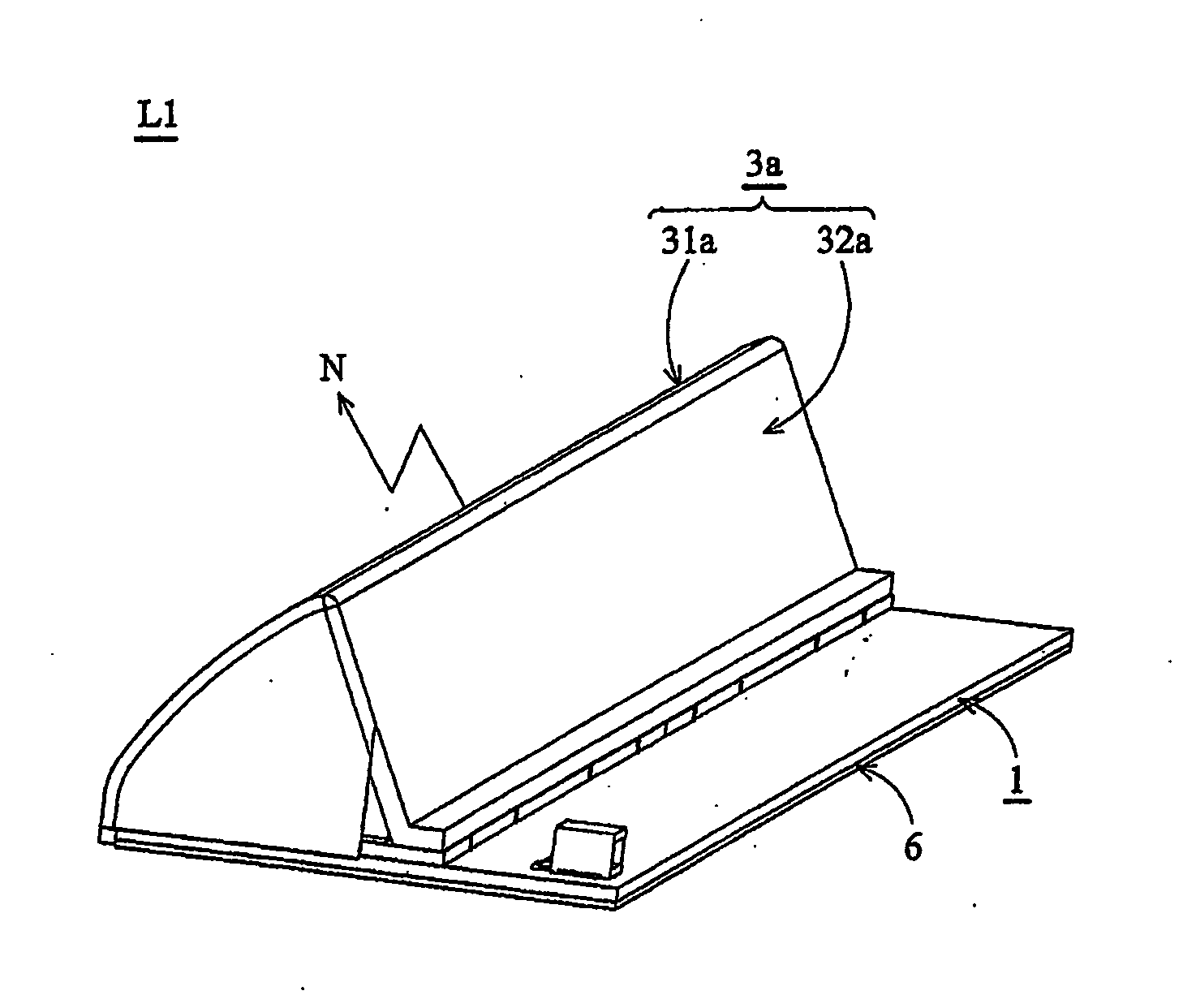
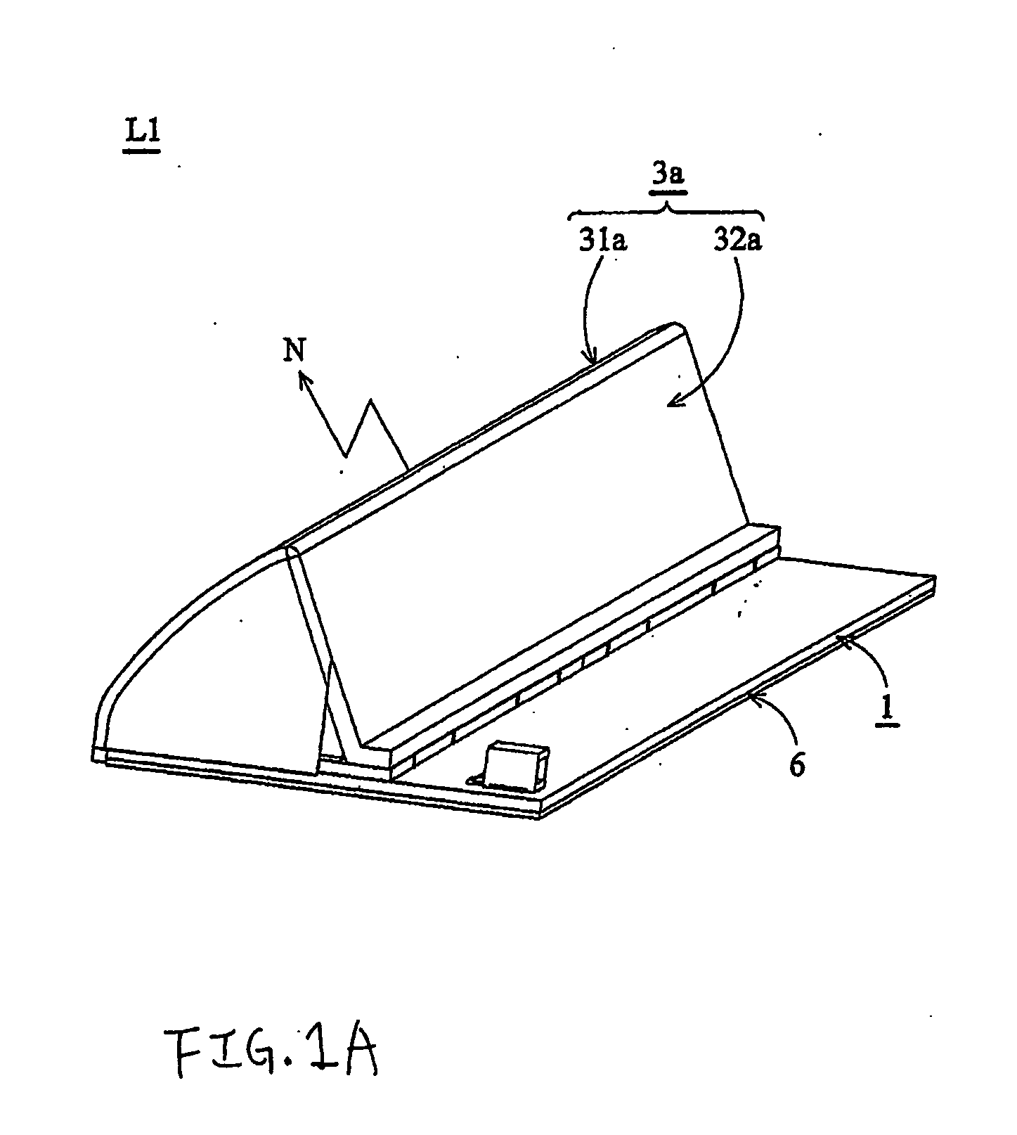
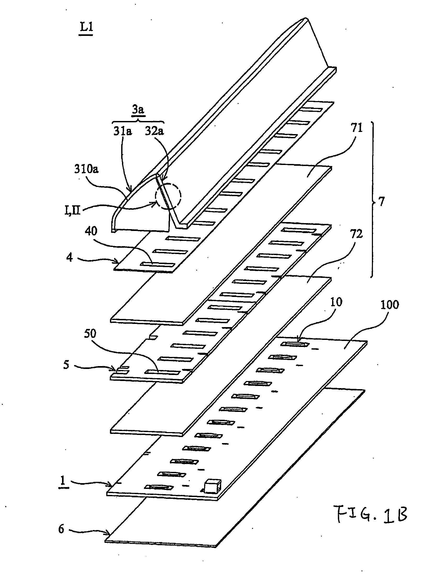
[0033]FIG. 1A is a perspective view illustrating an illuminating device L1 comprising a circuit unit 1 on which at least one light source is attached, and a transparent shell 3a, according to one embodiment of the present invention. In one embodiment, the illuminating device L1 comprises a circuit unit 1, a transparent shell 3a and a heat sink plate 6 attached to the circuit unit 1. The circuit unit 1 may further comprise an appropriate number of LEDs soldered to its upper surface. The transparent shell 3a comprises a diffusion portion 31a and a reflection portion 32a. The heat sink plate 6 is made of a material that can efficiently dissipate heat, generated mainly by the LEDs soldered on the circuit unit 1, while projecting light, reflected by the reflection portion 32a of the transparent shell 3a, along a desirable direction N through the diffusion portion 31a of the transparent shell 3a. According to an embodiment of the present invention, the illuminating device L1 may be connec...


PUM


Abstract

An illuminating device equipped with an integrated one-piece transparent shell is provided according to one embodiment of the invention. The illuminating device may be connected to a television, a computer monitor or an audio apparatus such that the illuminating device projects ambient light onto background walls or surroundings in order to improve the comfort and viewing experience. In one embodiment of the invention, an illuminating device used for ambient light comprises: a circuit unit comprising a plurality of light sources emitting light and a transceiver accepting display information; a shell coupled with said circuit unit; wherein a portion of said shell is transparent; wherein the shell comprises a diffusion portion and a reflection portion, and wherein a portion of said emitted light is reflected by said reflection portion and dispersed by said diffusion portion.

Description

CROSS-REFERENCE TO RELATED APPLICATION [0001] This application is based on Taiwanese Patent Application No. 094221359 filed Dec. 8, 2005 including specification, claims, drawings and summary. The disclosure to the above Taiwanese patent application is incorporated herein by reference in its entirety. FIELD OF THE INVENTION [0002] The present invention generally relates to light sources, and more specifically certain embodiments of the present invention relate to light sources that provide concentrated light to an ambient environment. Such light sources may be used as a backlight for computer monitors, televisions, and audio apparatuses. BACKGROUND OF THE INVENTION [0003] Televisions and computer monitors utilize flat panels and digital techniques to improve dimensional size and display quality, and many more improvements are still under development, such as 3D digital comb filters and 3D digital noise reduction. Recently, research and development efforts for display apparatus are di...

Claims


Application Information

Patent Timeline
IPC IPC(8): F21V7/00
CPCF21S10/02F21V3/04F21V11/14F21V13/12F21Y2101/02F21Y2115/10
Inventor LIN, WAN-CHUNTAN, TZY-CHANGHSIEH, KUN-HANCHANG, KAI-CHI
Owner UPEC ELECTRONICS CORP
Why Eureka
Try Eureka