
Returning transmission cutting machine

A cutting machine and driving motor technology, applied in the field of electromechanical engineering, can solve the problems of small size and power reduction, and achieve the effect of simple installation, simple operation and maintenance, and small occupied space

Active Publication Date: 2016-02-03
蚌埠奥德压缩机工贸有限公司
View PDF8 Cites 1 Cited by
  • Summary
  • Abstract
  • Description
  • Claims
  • Application Information

AI Technical Summary

Problems solved by technology

[0002] At present, my country's construction industry construction sites and professional steel bar processing workshops (sections) increasingly need a small, light, convenient, and energy-saving steel bar cutting machine. Up to now, no ideal steel bar cutting machine has been developed. Most of the medium-sized steel bar cutting machines are similar to the reduction of large models, but the volume and power are not much reduced.

Method used


Image

  • Returning transmission cutting machine
  • Returning transmission cutting machine

Examples


Embodiment Construction

[0013] In order to make the object, technical solution and advantages of the present invention clearer, the present invention will be further described in detail below in conjunction with the accompanying drawings and embodiments. It should be understood that the specific embodiments described here are only used to explain the present invention, not to limit the present invention.

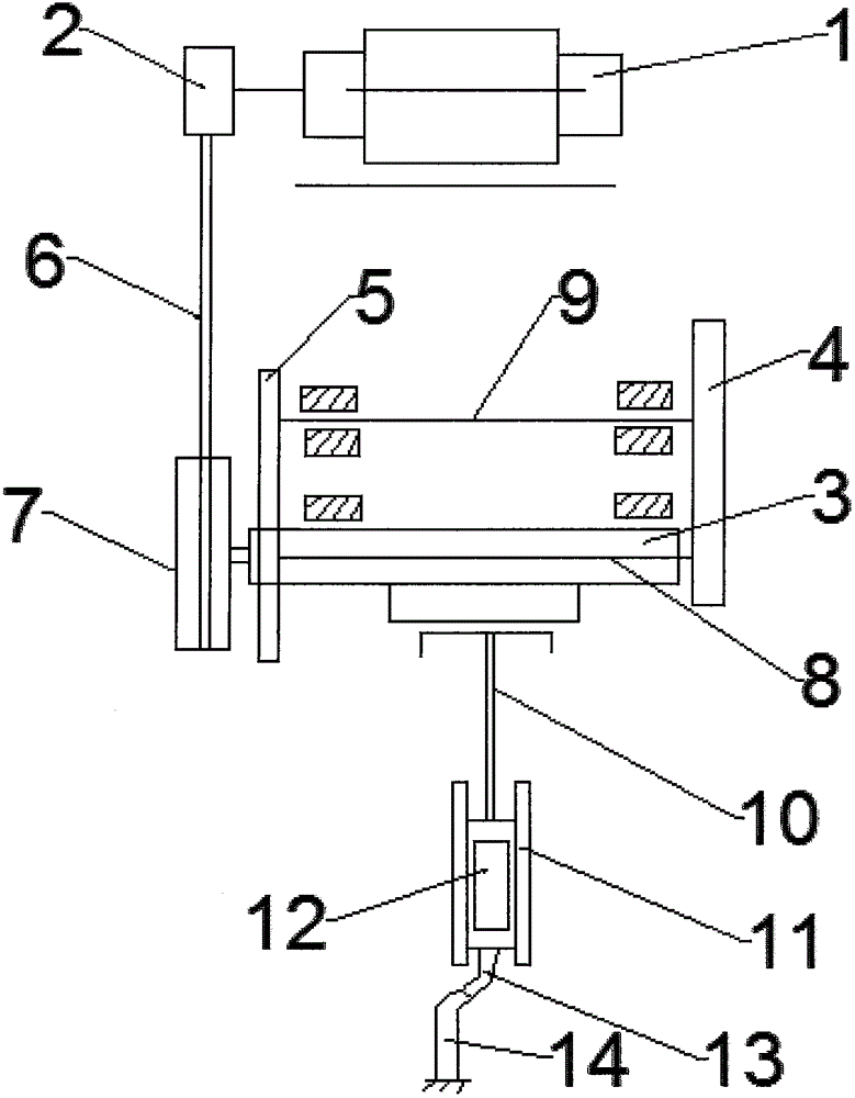
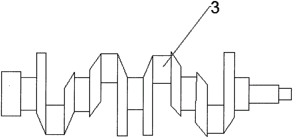
[0014] Such as figure 1 and 2 As shown, a return type transmission cutting machine includes a drive motor 1, a pulley shaft 2, an eccentric crankshaft 3, a primary gear 4 and a secondary gear 6, the drive motor 1 is connected to the pulley shaft 2, and the pulley shaft 2. The flywheel 7 is connected with the V-belt 6. The flywheel 7 is connected with the eccentric crankshaft 3. The eccentric crankshaft 3 is provided with a primary gear shaft 8. The primary gear shaft 8 is connected with the primary gear 4. The secondary gear 5 The secondary gear shaft 9 is connected, and the eccentric crankshaft ...


PUM

PropertyMeasurementUnit
poweraaaaaaaaaa

Abstract

The invention relates to the field of electromechanical engineering, in particular to a returning transmission cutting machine. The returning transmission cutting machine comprises a driving motor, a belt axle, an eccentric crankshaft, a primary gear and a secondary gear, wherein the driving motor is connected with the belt axle; the belt axle is connected with a flywheel through a triangle belt; the flywheel is connected with the eccentric crankshaft; a primary gear shaft is arranged on the eccentric crankshaft, and is connected with the primary gear; the secondary gear is connected with a secondary gear shaft; the eccentric crankshaft is connected with a connecting rod; the connecting rod is connected with a slideway; a sliding block is arranged on the slideway; the slideway is connected with a moving knife; and the moving knife is connected with a stationary knife. Compared with the traditional cutting machine, the structural design of the returning transmission cutting machine is more compact, and the returning transmission cutting machine has the characteristics of light weight, simplicity and convenience in mounting, small floor area, safety, reliability, simplicity in operation and maintenance, etc.

Description

technical field [0001] The invention relates to the field of electromechanical engineering, in particular to a regressive transmission cutting machine. Background technique [0002] At present, my country's construction industry construction sites and professional steel bar processing workshops (sections) increasingly need a small, light, convenient, and energy-saving steel bar cutting machine. Up to now, no ideal steel bar cutting machine has been developed. Most of the medium-sized steel bar cutting machines are similar to the reduction of large models, but the volume and power have dropped little. For this, it is very necessary to design a kind of small-sized steel bar cutting machine. Contents of the invention [0003] In view of the above problems, the present invention provides a regressive drive cutting machine with a more compact structure, and the changed crankshaft is a hollow eccentric crankshaft, and the hollow shaft has the ability to withstand high bending an...

Claims


Application Information

Patent Timeline
Patent Type & Authority Applications(China)
IPC IPC(8): B21F11/00
CPCB21F11/00
Inventor 张志通张洁李晓颖
Owner 蚌埠奥德压缩机工贸有限公司
Learn More