Simple clamping equipment

A simple and clamping technology, applied in binding, printing and other directions, can solve the problems of inconvenient operation and cumbersome operation, and achieve the effect of simple operation, wide applicability, and simple bill fixing method.

Inactive Publication Date: 2016-02-03
东莞市拓尔玛特自动化科技有限公司
View PDF5 Cites 4 Cited by
  • Summary
  • Abstract
  • Description
  • Claims
  • Application Information

AI Technical Summary

Problems solved by technology

Generally speaking, people clamp a clip at the left and right positions of the head of a stack of bills to ensure the stability of the clamping, but not only the operation is cumbersome, but even if the corresponding automatic assembly equipment is used for transportation Clamping also requires the operator to install the clips into the left and right parts of the automatic assembly equipment before use, which is inconvenient to operate

Method used


Image

  • Simple clamping equipment
  • Simple clamping equipment
  • Simple clamping equipment

Examples


Embodiment Construction

[0018] In order to make the technical means, creative features, goals and effects achieved by the present invention easy to understand, the present invention will be further elaborated below.

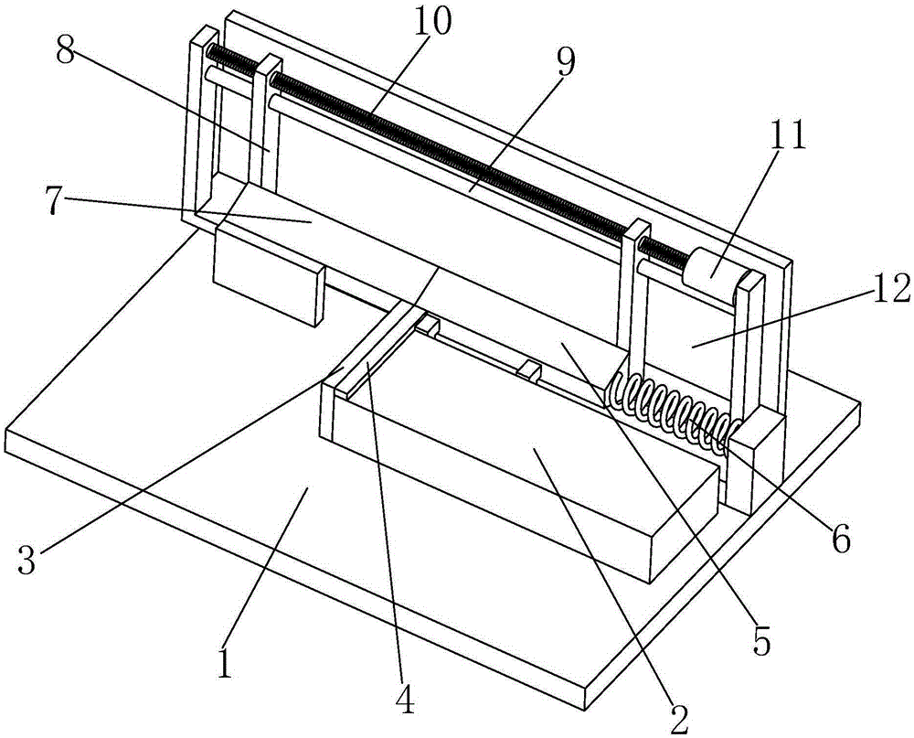
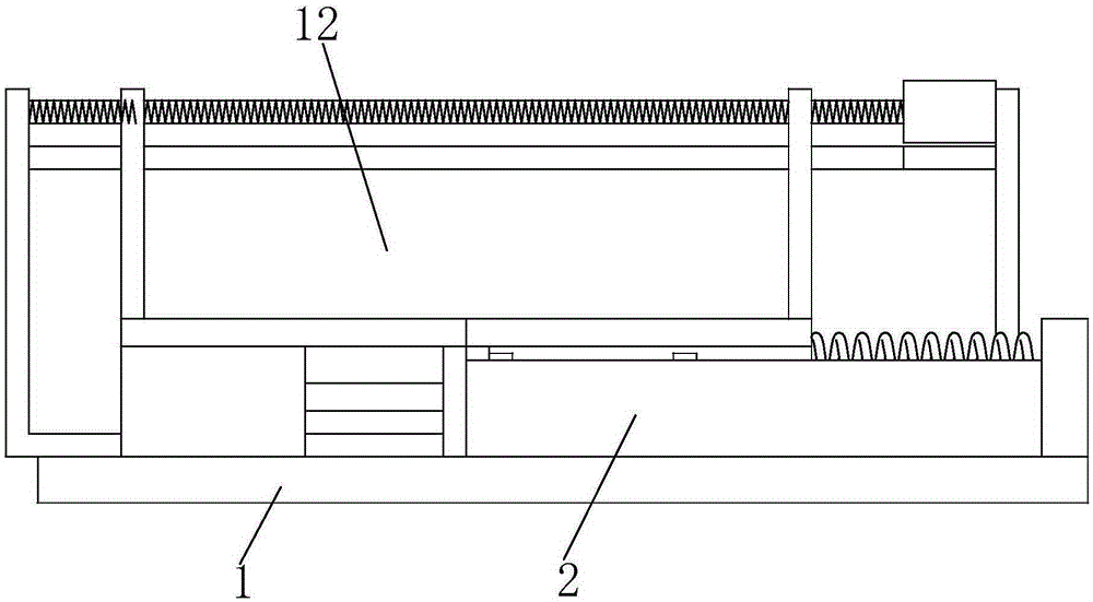
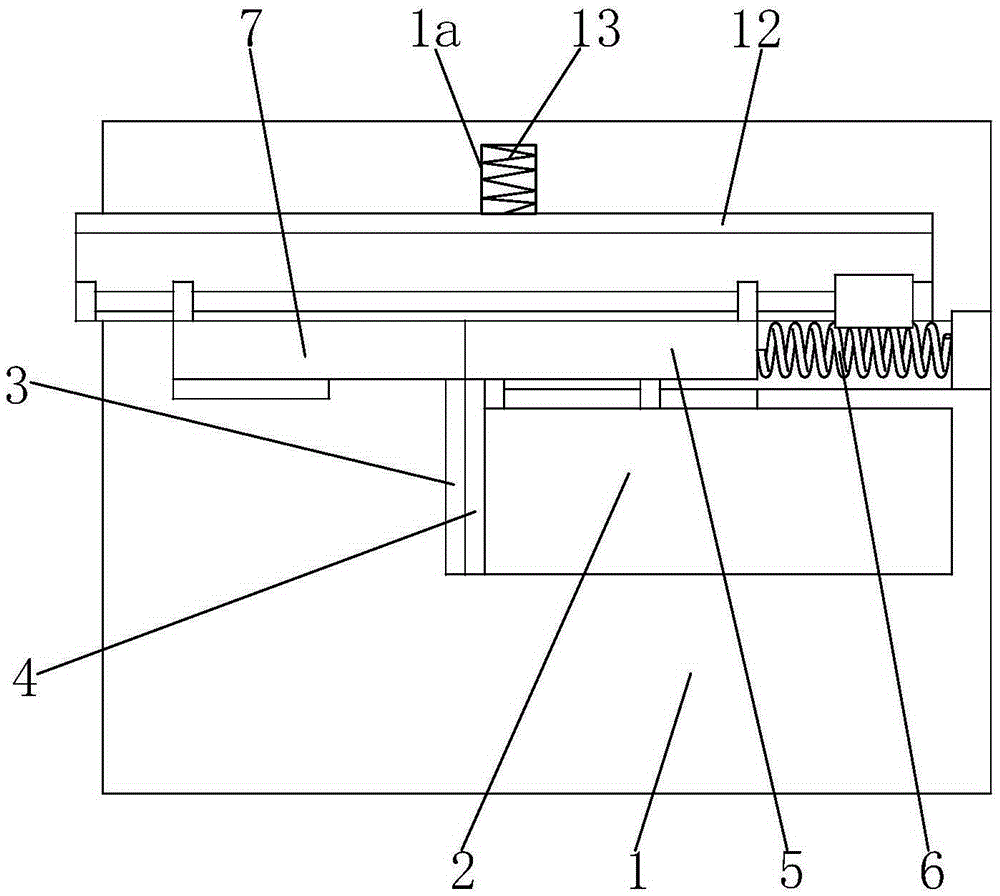
[0019] Such as Figure 1 to Figure 3 As shown, a simple clamping device mainly includes a base plate 1, a placement table 2 is provided on the base plate 1, a left positioning plate 3 is provided on the placement table 2, and the left positioning plate 3 The right end is abutted with a clamping plate 4 installed on the display table 2 in a horizontal sliding manner, and the rear end of the clamping plate 4 is welded with a right column 5 with a trapezoidal cross section and a square prism shape as a whole. 5 right ends are connected with spring 6.

[0020] The left end of the right pillar 5 is abutted against a left pillar 7 whose shape matches the shape of the right pillar 5 , and the left pillar 7 is fixedly mounted on the base plate 1 .

[0021] The placing table 2 is used to place...


PUM


Abstract

The invention relates to simple clamping equipment. The simple clamping equipment mainly comprises a base board; a placement table is arranged on the base board and provided with a left positioning board; the right end of the left positioning board abuts against a clamping board in a combined mode; a right table column is welded to the rear end of the clamping board; the right end of the right table column is connected with a spring; the left end of the right table column abuts against a left table column in a combined mode; the rear end of the left table column and the rear end of the right table column abut against drive rods in a combined mode respectively; the upper portions of the drive rods are provided with a polish rod and a composite lead screw; the composite lead screw is connected with a motor. An adjusting groove is formed in the rear end of the base board and is internally provided with a main installation base in a sliding mode; a reset spring is arranged between the main installation base and the rear end of the adjusting groove. The two drive rods are driven in a lead screw driving mode to drive a clamp for centering movement, and the effect of automatically clamping bills is achieved. The simple clamping equipment further has the characteristics that the clamp filling mode is simple and operation is simple and has the advantages that the bill fixing mode is simple and applicability is wide.

Description

technical field [0001] The invention relates to the field of file classification and processing, in particular to a simple clamping device. Background technique [0002] In an enterprise, every month the company's financial personnel need to summarize and classify the various financial bills of the enterprise as a whole, and then clamp and fix the classified piles of bills with clips. Generally speaking, people clamp a clip at the left and right positions of the head of a stack of bills to ensure the stability of the clamping, but not only the operation is cumbersome, but even if the corresponding automatic assembly equipment is used for transportation Clamping also requires the operator to install the clips into the left and right two clamping conveyors of the automatic assembly equipment before use, which is inconvenient to operate. Contents of the invention [0003] Aiming at the defects of the above-mentioned technologies, the present invention proposes a simple clamp...

Claims


Application Information

Patent Timeline
Patent Type & Authority Applications(China)
IPC IPC(8): B42F1/02
Inventor 付建邹洪
Owner 东莞市拓尔玛特自动化科技有限公司
Why Eureka
Try Eureka