Wart resection equipment for dermatology department

A dermatology and wart technology, applied in the field of excision equipment, can solve problems such as troublesome operation, inability to automatically cut, and danger

Pending Publication Date: 2022-03-15
李有新
View PDF0 Cites 0 Cited by
  • Summary
  • Abstract
  • Description
  • Claims
  • Application Information

AI Technical Summary

Problems solved by technology

[0005] In order to overcome the shortcomings of the existing cutting technology, which is cumbersome to operate, relatively dangerous, and cannot be cut automatically, the technical

Method used


Image

  • Wart resection equipment for dermatology department
  • Wart resection equipment for dermatology department
  • Wart resection equipment for dermatology department

Examples


Embodiment 1

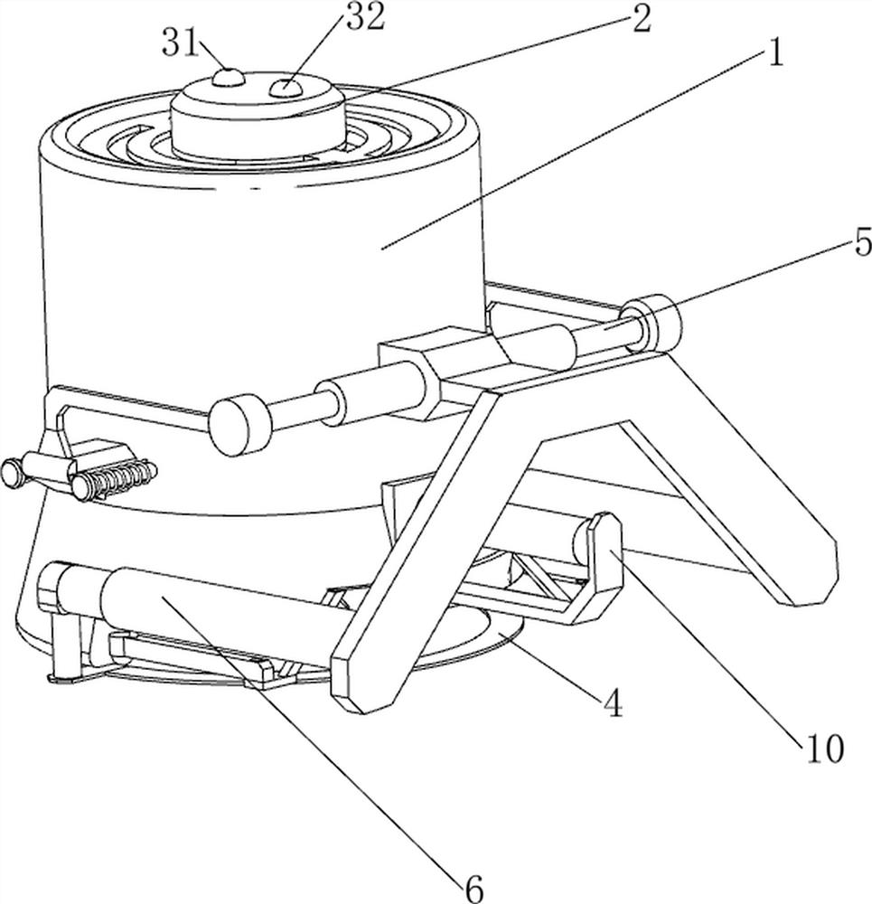
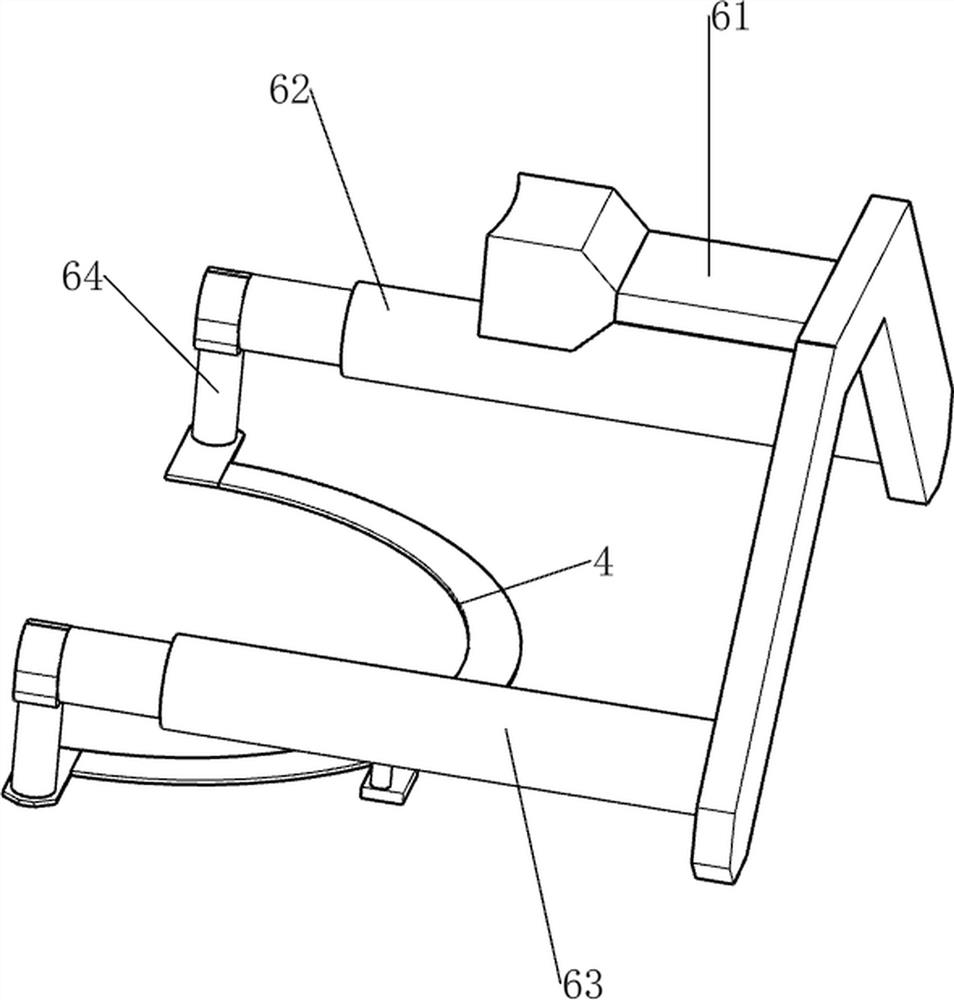
[0033] A wart excision device for dermatology, such as figure 1 , figure 2 , image 3 , Figure 4 , Figure 10 and Figure 11 As shown, it includes a casing 1, a control box 2, a first contact switch 31, a second contact switch 32, a cutter 4, a clamping mechanism 5 and a cutting mechanism 6. The top of the casing 1 is provided with a control box 2, and inside the control box 2 A switching power supply, a control module and a power supply module are installed, and the switching power supply supplies power to the dermatological wart excision device. The output end of the switching power supply is electrically connected to the power supply module. The power supply module is connected to a main power switch through a line, and the control module and The power supply module is electrically connected; the control module is connected with a DS1302 clock circuit and a 24C02 circuit, and a first contact switch 31 is provided on the rear side of the top of the control box 2, and t...

Embodiment 2

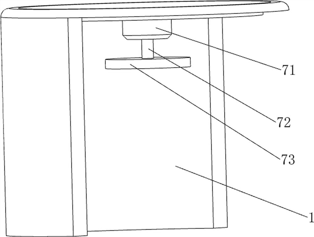
[0038] On the basis of Example 1, such as figure 1 , figure 2 , Figure 5 , Image 6 , Figure 7 , Figure 8 , Figure 9 , Figure 10 and Figure 11 As shown, a rotating mechanism 7 is also included. The rotating mechanism 7 includes a geared motor 71, a first rotating shaft 72 and a rotating plate 73. A geared motor 71 is installed on the top side inside the housing 1. The geared motor 71 is connected to the control module through a relay control module. , the output shaft of the reduction motor 71 is provided with a first rotating shaft 72 , and the bottom of the first rotating shaft 72 is provided with a rotating plate 73 .

[0039] Also include hold-down mechanism 8, hold-down mechanism 8 includes the 3rd electric push rod 81, the first push plate 82, the second telescoping rod 83, the second spring 84, liquid cylinder 85, hose 86, ball 87 and pressure Sensor 88, the bottom of rotating plate 73 is provided with the 3rd electric push rod 81, and the 3rd electric pu...


PUM


Abstract

The invention relates to excision equipment, in particular to wart excision equipment for the dermatology department. The wart resection equipment for the dermatology department can automatically smear disinfection liquid medicine, can automatically clamp and can be used for cutting at present. The wart resection equipment for the dermatology department comprises a shell and a control box, and the control box is arranged at the top of the shell; the first contact switch is arranged on the control box, and the first contact switch is electrically connected with the control module; the second contact switch is arranged on the control box, and the second contact switch is electrically connected with the control module; the clamping mechanism is arranged on the shell; the cutting mechanism is arranged on the clamping mechanism; and the cutter is arranged on the cutting mechanism. According to the wart cutting device, by arranging the clamping mechanism, the clamping mechanism operates and clamps a wart body, so that the automatic clamping effect is achieved, and subsequent wart body cutting is facilitated.

Description

technical field [0001] The invention relates to a resection device, in particular to a wart resection device for dermatology. Background technique [0002] Warts generally refer to warts, also known as millipedes and warts. Because warts are difficult to cure with drugs, the cycle is long, and they are prone to recurrence, the most commonly used treatment method is wart excision surgery. The doctor holds the wart with tweezers in one hand, and cuts the wart with a scalpel in the other. The dirty blood inside will gush out quickly, which is not conducive to medical staff wiping and cleaning the knife; for inexperienced doctors, there is also a hidden danger of directly pinching the wart body with tweezers and causing dirty blood to splatter. [0003] Patent application CN212853582U, published on 2021.04.02, discloses a wart cutting device for dermatology, including a support rod, a chute, a slider, an empty cylinder, a piston, a piston rod, a catheter, a suction head and a c...

Claims


Application Information

Patent Timeline
IPC IPC(8): A61B17/3205A61B90/00A61B90/14A61M35/00
CPCA61B17/3205A61B90/14A61M35/20A61B90/06A61B2017/00774A61B2090/064A61B2090/061
Inventor 李有新
Owner 李有新
Why Eureka
Try Eureka