
A furnace tube rotation and intermittent feeding type display rack

A technology for placing racks and furnace tubes, applied in the directions of transportation, packaging, rollers, etc., can solve the problems of poor rigidity, fast heat dissipation of furnace tubes, low operation efficiency, etc., and achieve good economic and social benefits, uniform heat dissipation and cooling, The effect of improving quality

Active Publication Date: 2017-09-19
江苏博颂能源科技有限公司 +1
View PDF7 Cites 0 Cited by
  • Summary
  • Abstract
  • Description
  • Claims
  • Application Information

AI Technical Summary

Problems solved by technology

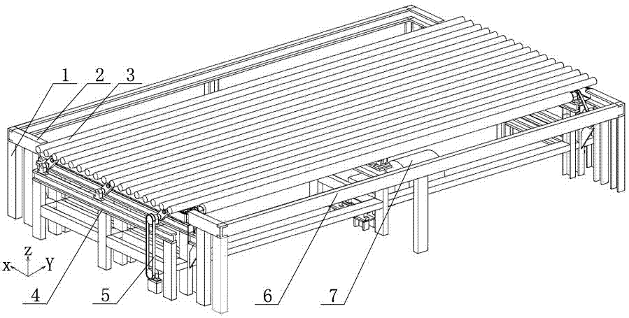
The furnace tube rack currently used in production is just an ordinary frame welded by channel steel, which has the following defects: 1), the furnace tube is placed statically on the rack, and only two ends and There are three supports in the middle part. Since the furnace tube is slender, the temperature is about 600°C to 700°C when it is just pulled out, and the rigidity is poor. After standing on such a shelf for a period of time, it will bend down due to gravity; 2 ), the heat dissipation speed is fast at the contact between the furnace tube and the placement rack, resulting in uneven cooling and shrinkage throughout the entire length, which will aggravate the bending deformation of the furnace tube; 3), the placement rack needs to be manually pushed forward sequentially. Let the furnace tube enter the shot blasting process, and also make room for the next furnace tube to be pulled out, and the operation efficiency is low

Method used


Image

  • A furnace tube rotation and intermittent feeding type display rack
  • A furnace tube rotation and intermittent feeding type display rack
  • A furnace tube rotation and intermittent feeding type display rack

Examples


Embodiment Construction

[0020] The present invention will be further described below in conjunction with accompanying drawing, but not as limiting the present invention:

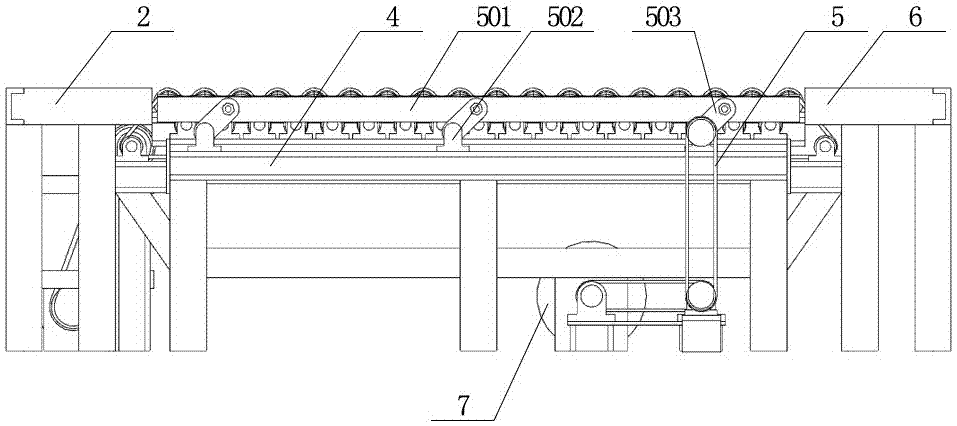
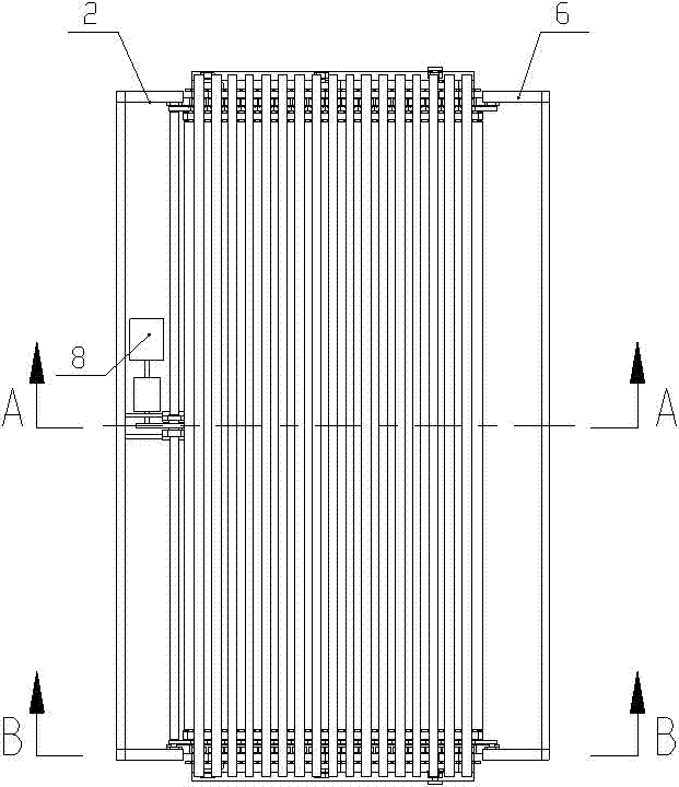
[0021]A furnace tube rotation and intermittent feeding type display rack, including a display rack 1, a power source B8 is provided at the lower left side of the placement rack 1, and the placement rack 1 is composed of the left rear guide section 2, The middle middle placement section 4 is composed of the front guide section 6 on the right side. The front guide section 6 is used to temporarily place the furnace tube 3 that has just been pulled out, and the rear guide section 2 is used to place the furnace tube 3 just removed from the middle placement section. The furnace tube 3 sent over; the middle placement section 4 is provided with support pieces symmetrically arranged front and back, and the support pieces are arranged along the X-axis direction, and the support pieces arranged symmetrically front and back are support piece A4...


PUM


Abstract

The invention discloses a furnace tube rotation and intermittent feeding type display frame. A power source B is arranged at the lower left side of the display frame. The front guide section on the side is composed of front and rear guide sections, and the middle section is provided with support pieces arranged symmetrically in front and back. Both ends are provided with a support frame, and the top of the support frame is provided with a bearing seat, the bearing seat at the top of the support sheet C is higher than the bearing seat at the top of the support sheet B, and the bearing seat at the top of the support sheet C and the bearing seat at the top of the support sheet B are arranged at intervals; The supporting idler sheet is arranged in the middle of the middle placement section. In the present invention, the furnace tube is rotated and fed forward intermittently, so that the furnace tube can be placed in a proper supporting state on the placement rack, and uniform heat dissipation and cooling over the entire length are realized, and the furnace tube is continuously rotated around its axis during the cooling process. The deformation is reduced and the quality of the furnace tube is improved.

Description

technical field [0001] The invention belongs to the field of centrifugal casting process equipment, in particular to a furnace tube rotation and intermittent feeding type display rack. Background technique [0002] After the centrifugal casting furnace tube is pulled out from the mold cylinder, it needs to be placed on a rack to cool down, and then shot blasting is performed. The furnace tube has certain roundness and straightness requirements. The furnace tube rack currently used in production is just an ordinary frame welded by channel steel, which has the following defects: 1), the furnace tube is placed statically on the rack, and only two ends and There are three supports in the middle part. Since the furnace tube is slender, the temperature is about 600°C to 700°C when it is just pulled out, and the rigidity is poor. After standing on such a shelf for a period of time, it will bend down due to gravity; 2 ), the heat dissipation speed is fast at the contact between the...

Claims


Application Information

Patent Timeline
Patent Type & Authority Patents(China)
IPC IPC(8): B65G13/07
Inventor 张凤娇吴玉同杨建明张军李晓琛吴巍
Owner 江苏博颂能源科技有限公司
Learn More