Tube arranging device for steel tube fork of loader

A technology of loader and steel pipe, applied in the direction of lifting device, etc., can solve the problems of single working mode and low efficiency, and achieve the effect of improving work efficiency, reducing use cost and operability.

Active Publication Date: 2016-02-03
GUANGXI LIUGONG MASCH CO LTD +1
View PDF6 Cites 4 Cited by
  • Summary
  • Abstract
  • Description
  • Claims
  • Application Information

AI Technical Summary

Problems solved by technology

[0003] The purpose of the patent of the present invention is to invent a new mechanism for the steel pipe fork in view of the single working mode and low efficiency of the existing steel pipe holding fork. on steel pipe

Method used


Image

  • Tube arranging device for steel tube fork of loader
  • Tube arranging device for steel tube fork of loader
  • Tube arranging device for steel tube fork of loader

Examples


Embodiment 1

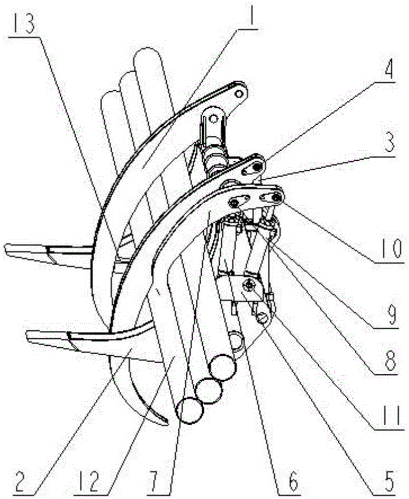
[0026] Such as figure 1 As shown, a loader steel pipe fork pipe device mainly includes the upper fork body 1, the lower fork body 2, and the hydraulic cylinder I3 that controls the upper fork body 1 and realizes the cohesion and opening of the upper fork body 1 and the lower fork body 2 , the rear end of the upper fork body 1 is connected with the hydraulic cylinder I3, and the upper fork body 1 is driven to rotate around the pin shaft 4 through the hydraulic oil cylinder I3; The mechanism includes a fixed support 5, a lifting cylinder 6, a hydraulic cylinder II 9 and a branch fork 7, the fixed support 5 is fixed on the outer surface of the lower fork body 2, and each of the lifting cylinder 6 and the hydraulic cylinder II 9 has one end connected to the fixed support 5, The other end and the branching fork 7, the lifting cylinder 6 and the hydraulic cylinder II 9 jointly control the cohesion and opening of the branching fork 7.

[0027] In the steel pipe fork arrangement devi...

Embodiment 2

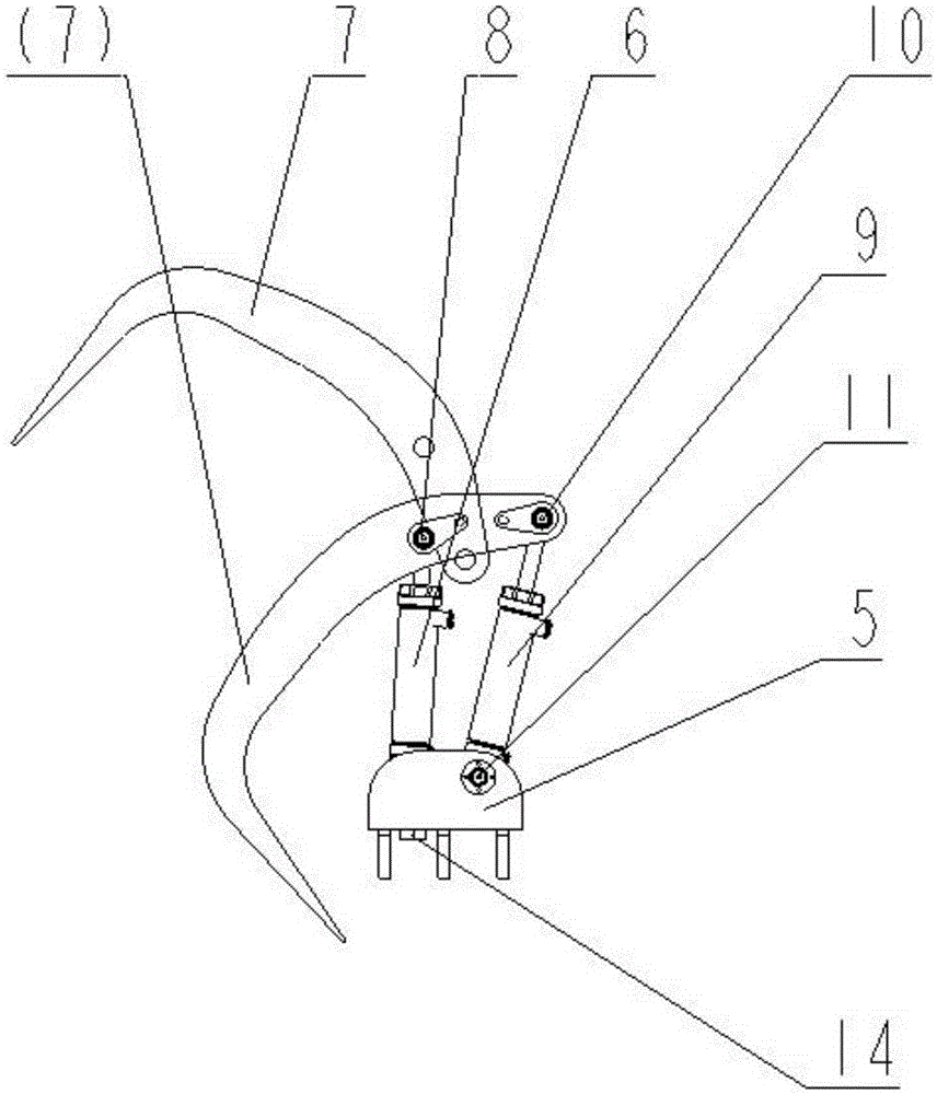
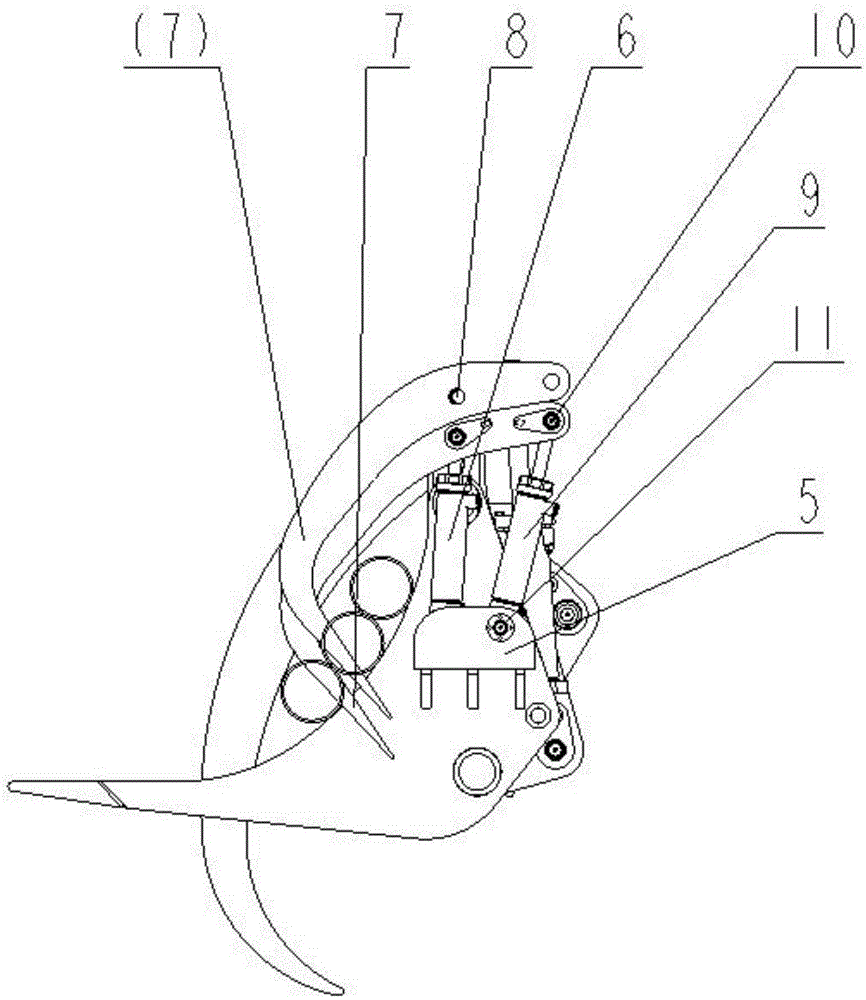
[0029] The difference from Embodiment 1 is: the branching fork 7 is provided with a middle pin 8 and a pin shaft I10, the cylinder end of the lifting cylinder 6 is fixed on the fixed support 5, and the cylinder end does not have any degree of freedom, and the piston rod of the lifting cylinder 6 The end is connected with the middle pin 8 of the branching fork 7, and the lifting cylinder 6 can only do lifting movement in the vertical direction; the piston rod of the hydraulic cylinder II9 and the branching fork 7 are connected through the pin shaft I10, and the cylinder body of the hydraulic cylinder II9 is ​​connected through the pin shaft Ⅱ11 is connected with the fixed support 5, and both ends of the hydraulic cylinder Ⅱ9 have degrees of freedom and can rotate around pin shafts Ⅰ10 and Ⅱ11.

Embodiment 3

[0031] The difference from embodiment 2 is that the branching fork 7 is composed of left support plate 7-2, right support plate 7-1, upper sealing plate 7-3, and lower sealing plate 7-4. The sealing plate is welded, and there are two hinged holes on the branch fork 7, and the lifting cylinder 6 and the hydraulic cylinder II9 are respectively connected through the middle pin 8 and the pin shaft I10.


PUM


Abstract

The invention discloses a tube arranging device for a steel tube fork of a loader. The device comprises an upper fork body (1), a lower fork body (2), a hydraulic cylinder I (3) and a set of four-connecting-bar mechanism, wherein the hydraulic cylinder I (3) controls the upper fork body (1) and achieves closing and opening of the upper fork body (1) and the lower fork body (2); the four-connecting-bar mechanism is arranged on the outer end faces of two sides of the lower fork body (2) symmetrically and comprises a fixing support (5), a lifting cylinder (6), a hydraulic cylinder II (9) and a tube separating fork (7); the fixing support (5) is fixed on the outer side face of the lower fork body (2); one end of the lifting cylinder (6) and one end of the hydraulic cylinder II (9) are connected with the fixing support (5); the other end of the lifting cylinder (6) and the other end of the hydraulic cylinder II (9) are connected with the tube separating fork (7); and the lifting cylinder (6) and the hydraulic cylinder II (9) together control the closing and opening of the tube separating fork (7). According to the device, separation arrangement of steel tubes can be achieved; a plurality of steel tubes can be clamped for one time; and the steel tubes can be placed on a steel tube tool one by one.

Description

technical field [0001] The patent of the present invention is a new holding fork, especially relates to a multifunctional holding fork for loading and unloading steel pipes. Background technique [0002] With the diversification of the working conditions of the loader, the special attachments suitable for the loader are also constantly being developed. As a special attachment, the steel pipe fork of the loader is used in ports, urban construction and other places, and is mainly used for the handling of steel pipes. , display, etc. The steel pipe fork is a special attachment that mainly meets the needs of the working conditions with simple functions such as picking up, moving, and placing the steel pipe. Therefore, the steel pipe fork loader is still favored by customers in these working conditions and can be widely used. Existing steel pipe forks usually consist of an upper fork body, a lower fork body and a control pipeline. The lower fork body is mostly L-shaped, and the...

Claims


Application Information

Patent Timeline
Patent Type & Authority Applications(China)
IPC IPC(8): B66F9/18B66F9/22
Inventor 陈玉杰丁文勇王涛区思榜石磊邓敏边心文石军锋
Owner GUANGXI LIUGONG MASCH CO LTD
Why Eureka
Try Eureka