A construction method of a concrete beam cross connection structure provided with tension reinforcement

A technology for tensioning steel bars and concrete beams, applied in building components, building structures, floor slabs, etc. The effect of mechanical performance, significant comprehensive benefit and improvement of project quality

Active Publication Date: 2017-09-19
南通欧本建筑科技有限公司
View PDF5 Cites 0 Cited by
  • Summary
  • Abstract
  • Description
  • Claims
  • Application Information

AI Technical Summary

Problems solved by technology

The disadvantages of the cast-in-place method are that the amount of scaffolding erection is large, the high-altitude operation is dangerous, the construction period is long, and it requires a lot of labor. With the rising labor costs, the traditional extensive construction method based on on-site operations Has seriously hindered the construction of a low-carbon and harmonious society
[0003] In terms of construction technology, the traditional concrete composite beam is made by cast-in-place technology. The construction of the upper layer can only be carried out after the lower structure has been poured and maintained. Moreover, it is greatly affected by objective factors such as weather, and the construction period is easy. be extended

Method used


Image

  • A construction method of a concrete beam cross connection structure provided with tension reinforcement
  • A construction method of a concrete beam cross connection structure provided with tension reinforcement
  • A construction method of a concrete beam cross connection structure provided with tension reinforcement

Examples


Embodiment Construction

[0029] In order to make the technical means, creative features, goals and effects of the present invention easy to understand, the present invention will be further described below in conjunction with specific illustrations.

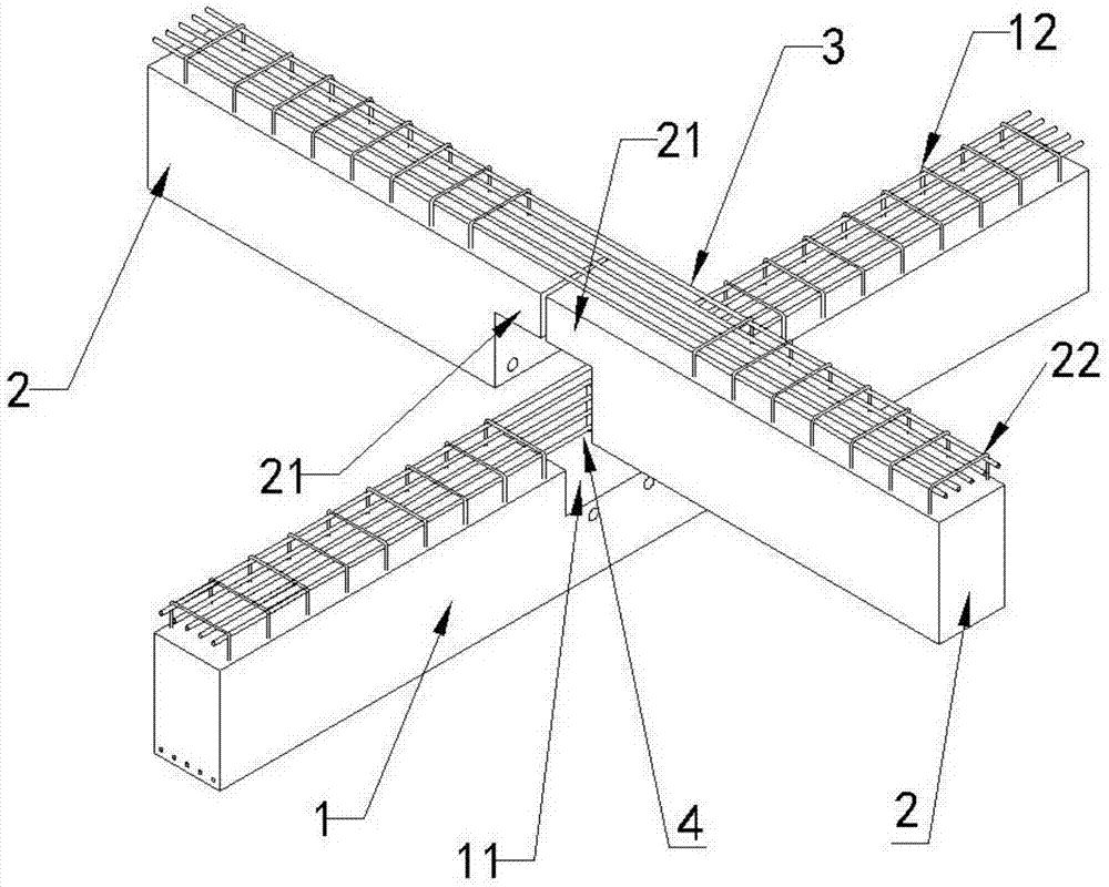
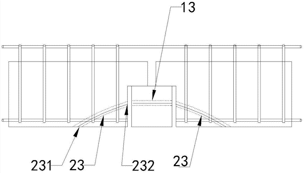
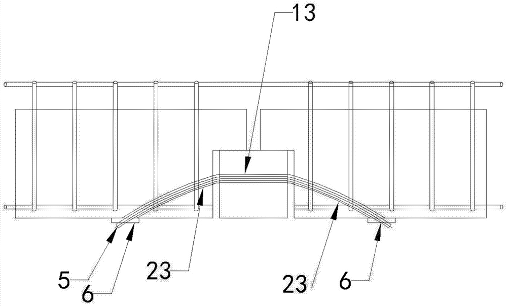
[0030] see Figure 1-4 , a concrete beam cross connection structure provided with tensile reinforcement, which includes a pre-cast concrete composite beam, the concrete composite beam includes a female beam 1 and a male beam 2, and the female beam 1 is installed between the adjacent main beams Between them, a mortise 11 extending along its thickness direction is reserved on the main body of the female beam 1, and a tenon 21 extending along the body is respectively formed on both ends of the male beam 2, and the male beams arranged symmetrically on both sides of the female beam 1 The tenons 21 of 2 are respectively inserted into the tenons and grooves 11 to form a cross structure. In order to ensure the flatness of the joint joints, in the design structur...


PUM


Abstract

The invention discloses a construction method for a concrete beam cross connection structure provided with tensile steel bars. The structure comprises a pre-cast concrete composite beam, and the concrete composite beam includes a female beam and a male beam connected by mortise and tenon, wherein the male beam The beam body at the end of the beam is formed with perforations respectively. After the tensioned steel bars pass through the perforations, the ends are tensioned and fixed by riveting plates, so that the bottom of the beam forms a continuous structure. In terms of construction methods, the concrete composite beam is prefabricated, and passed through the mother beam in turn. Installation, installation of public beams, fixing of connecting parts, fixing of tensioned steel bars, installation of floor layers and pouring are integrated into one process. Compared with traditional structures, precast concrete composite beams greatly guarantee the quality of components without requiring a lot of internal and external work. For the scaffolding project, the cost of the floor is reduced by more than 10%. Compared with the traditional construction technology, the construction period can be shortened by half, the safety is greatly improved, and the comprehensive benefits are extremely significant.

Description

technical field [0001] The invention relates to the field of building components, in particular to a construction method for a concrete beam cross connection structure provided with tensioned steel bars. Background technique [0002] Composite beams are set between the main beams, and usually formwork is cast on site to form a concrete frame structure. The disadvantages of the cast-in-place method are that the amount of scaffolding erection is large, the high-altitude operation is dangerous, the construction period is long, and it requires a lot of labor. With the rising labor costs, the traditional extensive construction method based on on-site operations Has seriously hindered the construction of a low-carbon, harmonious society. [0003] In terms of construction technology, the traditional concrete composite beam is made by cast-in-place technology. The construction of the upper layer can only be carried out after the lower structure has been poured and maintained. Moreo...

Claims


Application Information

Patent Timeline
Patent Type & Authority Patents(China)
IPC IPC(8): E04B1/21E04B5/14
Inventor 陈明
Owner 南通欧本建筑科技有限公司
Why Eureka
Try Eureka