Leakage-preventing structure

An anti-drip, valve body technology, applied in the direction of control valve, functional valve type, engine components, etc., can solve the problem that the water meter cannot measure the flow, cannot restrict the flow direction of the fluid, etc., and achieve the effect of preventing fluid backflow and avoiding losses.

Active Publication Date: 2016-02-03
TIANJIN GUOWEI FEEDING & DRAINAGE EQUIP MENT MFG
View PDF6 Cites 0 Cited by
  • Summary
  • Abstract
  • Description
  • Claims
  • Application Information

AI Technical Summary

Problems solved by technology

[0002] At present, due to the limitation of the sensitivity of the water meter, when the flow rate is small to a certain extent, the water meter cannot measure the flow rate. Therefore, water is received in the way of "thin water and long flow" to avoid the water fee that should be paid and cause losses to the water supplier.
Most of the existing valves can only simply control the opening and closing of the fluid channel, but cannot limit the flow direction of the fluid, and cannot prevent and avoid the backflow phenomenon that is prone to occur during the municipal tap water supply process.

Method used


Image

  • Leakage-preventing structure
  • Leakage-preventing structure
  • Leakage-preventing structure

Examples


Embodiment 1

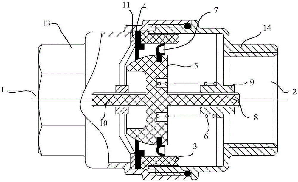
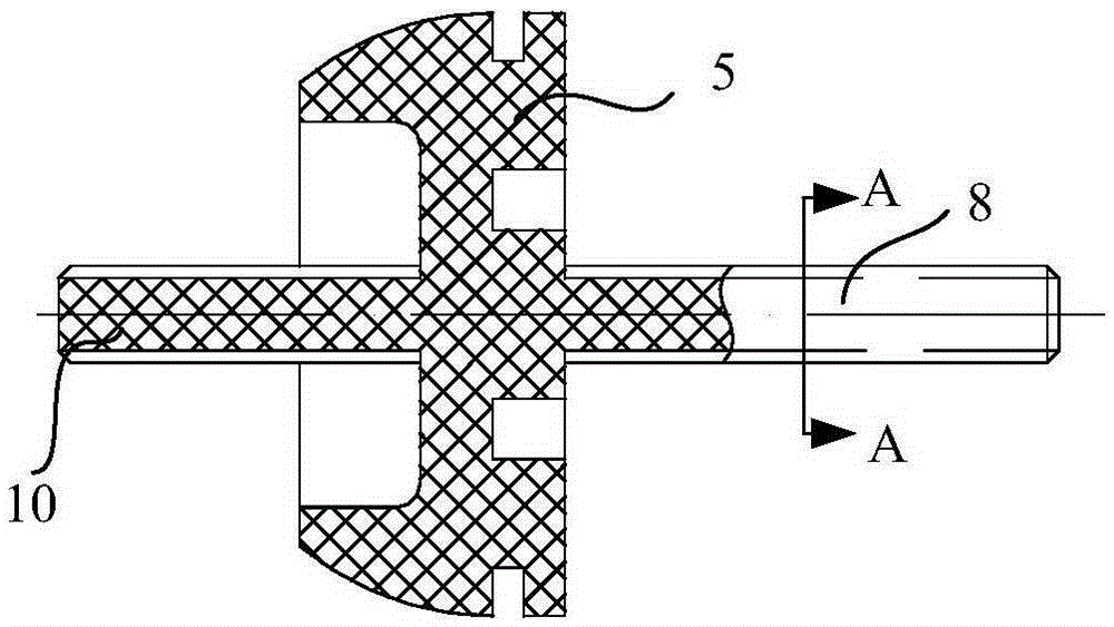
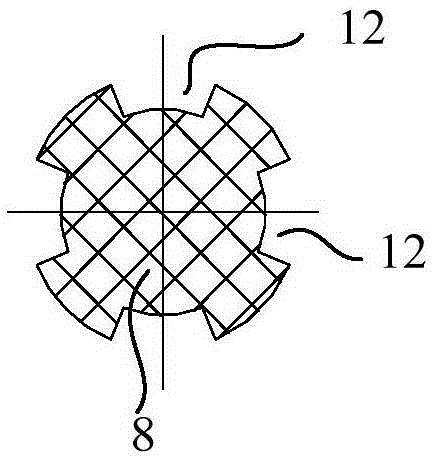
[0025] Such as figure 1 As shown, an anti-drip structure includes a valve body, the valve body is provided with a water inlet 1 and a water outlet 2, a valve seat 3 and a rubber pad 4 are fixed on the inner wall of the valve body, and a valve plate 5 is also provided inside the valve body , the valve plate 5 reciprocates along the water flow direction under the action of water pressure and the return device 6. When the valve plate 5 contacts the valve seat 3, it is a radial seal. When the valve plate 5 contacts the valve seat 3 and the rubber pad 4 at the same time, the rubber A sealed space is formed between the gasket 4, the valve seat 3 and the valve plate 5. When the water outlet 2 does not flow, the valve plate 5 is close to the rubber pad 4 under the action of the return device 6, and a sealed space is formed between the valve plate 5, the valve seat 3 and the rubber pad 4. When dripping occurs, due to the water outlet 2 The pressure drops, and the valve plate 5 moves t...

Embodiment 2

[0035] This embodiment is basically the same as the anti-drip structure in Embodiment 1, including a valve body, which is provided with a water inlet 1 and a water outlet 2, and a valve seat 3 and a rubber pad 4 are fixed on the inner wall of the valve body. A valve plate 5 is also provided, and the valve plate 5 reciprocates along the water flow direction under the action of the water pressure and the return device 6. When the valve plate 5 contacts with the valve seat 3, it is radially sealed. 4 When in contact at the same time, a sealed space is formed between the rubber pad 4, the valve seat 3 and the valve plate 5.

[0036] The difference is that the specific structure of the valve body is not limited, the specific location of the water inlet 1 and the water outlet 2 is not limited, the specific structure and fixing method of the valve seat 3, rubber pad 4, and valve plate 5 are not limited, and the valve plate 5 is not limited. The sealing scheme between the valve seat 3...


PUM


Abstract

The invention discloses a leakage-preventing structure and relates to the technical field of valves. The leakage-preventing structure comprises valve bodies. A water inlet and a water outlet are formed in the valve bodies respectively, valve seats and rubber mats are fixed to the inner walls of the valve bodies, valve plates are arranged in the valve bodies, do reciprocating motion in the water flow direction under the effect of the water pressure and the effect of resetting devices and are sealed in the radial direction when making contact with the valve seats, and sealing space is formed among the rubber mats, the valve seats and the valve plates when the valve plates make contact with the valve seats and the rubber mats at the same time. According to the invention, when water leaks, the pressure difference of the sealing space formed among the rubber mats, the valve seats and the valve plates is damaged, water flow larger than starting flow of a water meter is formed instantly so as to drive the water meter to measure the water flow, and therefore the phenomenon that the water meter cannot measure the water flow because the water flow is small is prevented, loss of water suppliers is avoided, backflow of fluid is prevented, and the flow direction of the fluid is limited.

Description

technical field [0001] The invention relates to the technical field of valves, in particular to an anti-drip structure. Background technique [0002] At present, due to the limitation of the sensitivity of the water meter, when the flow rate is small enough, the water meter cannot measure the flow rate. Therefore, water is received in the way of "thin water and long flow" to avoid the water fee that should be paid and cause losses to the water supplier. Most of the existing valves can only simply control the opening and closing of the fluid channel, but cannot limit the flow direction of the fluid, and cannot prevent and avoid the backflow phenomenon that easily occurs during the municipal tap water supply process. [0003] In order to solve the above problems, reduce the loss of the water supply side, and cherish the national wealth, it is necessary to design an anti-drip structure to prevent the phenomenon that the water meter cannot be rotated when the flow rate is small,...

Claims


Application Information

Patent Timeline
Patent Type & Authority Applications(China)
IPC IPC(8): F16K15/06
CPCF16K15/063
Inventor 刘永龚高石刘庆
Owner TIANJIN GUOWEI FEEDING & DRAINAGE EQUIP MENT MFG
Why Eureka
Try Eureka