Electronically-controlled tin melting device

An electronic manipulation and tin melting technology, applied in auxiliary devices, soldering irons, metal processing equipment, etc., can solve problems such as incomplete tin melting points, and achieve the effect of avoiding inconsistent standards

Inactive Publication Date: 2016-02-10
南京海联净化设备有限公司
View PDF0 Cites 0 Cited by
  • Summary
  • Abstract
  • Description
  • Claims
  • Application Information

AI Technical Summary

Problems solved by technology

Such a structure avoids the existing defect of incomplete tin melting points caused by the failure to grasp the standard and unified structure when melting tin

Method used


Image

  • Electronically-controlled tin melting device

Examples


Embodiment Construction

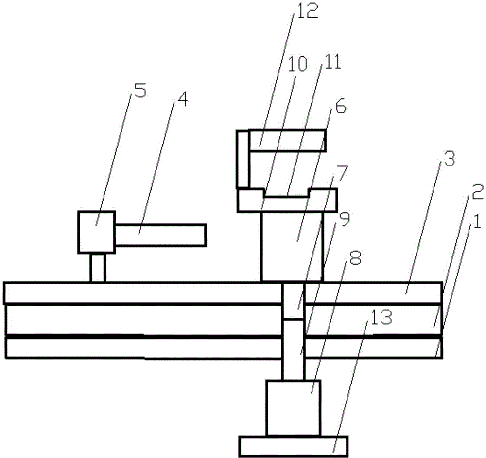
[0010] Below in conjunction with accompanying drawing, content of the invention will be further described:

[0011] refer to figure 1 As shown, the tin melting device under electronic manipulation includes a base 1, on which a block-shaped support block 2 is installed, and a conveyor belt 3 is installed on the support block 2, and a conveyor belt 3 is installed above the conveyor belt 3. The hydraulic gripper 4 driven by the hydraulic cylinder 5 is equipped with a square platform 6 on the conveyor belt 3, the bottom of the square platform 6 is connected with a connecting rod 7, the connecting rod 7 is connected with the motor shaft 9 of the motor 8, and the square platform 6 is installed to be The tin-melting component placement frame 10 is equipped with a concave hole 11 matching the outline of the tin-melting component on the pending-tin component placement frame 10, and an automatic tin-discharging electric soldering iron 12 is erected above the pending-tin component placem...


PUM


Abstract

An electronically-controlled tin melting device comprises a base. A blocky supporting piece block is mounted on the base, a conveying belt is mounted on the supporting piece block, and a hydraulic holder driven by a hydraulic air cylinder is mounted above the conveying belt. A square platform is mounted on the conveying belt, the bottom of the square platform is connected with a connecting rod, and the connecting rod is connected with a motor shaft of a motor. A carrying frame for elements to be subjected to tin melting is arranged on the square platform, a U-shaped hole matched with the contour of the elements to be subjected to tin melting is formed in the carrying frame for the elements to be subjected to tin melting, and automatic tin discharging electric soldering iron is erected above the carrying frame for the elements to be subjected to tin melting. By means of the structure, the defect that in the existing tin melting process, due to the fact that unified standard structures cannot be grasped usually, incomplete tin melting points are caused is overcome.

Description

technical field [0001] The invention belongs to the technical field of tin melting devices, in particular to an electronically controlled tin melting device. Background technique [0002] Existing electric soldering irons are widely used in the chip manufacturing industry as tin-melting devices. Soldering irons can be used as a fixed point for pins to be fully fixed. When the pins conduct heat and heat up, they can also dissipate heat. However, the operation of current electric soldering irons requires professional In this way, when melting tin, it is often impossible to grasp the standard and unified structure, resulting in the defect of incomplete melting point. Contents of the invention [0003] The object of the present invention is to provide an electronically controlled tin melting device, which includes a base, on which a block-shaped support block is installed, a conveyor belt is installed on the support block, and a hydraulic cylinder is installed above the convey...

Claims


Application Information

Patent Timeline
Patent Type & Authority Applications(China)
IPC IPC(8): B23K3/03B23K3/08
Inventor 陈优国
Owner 南京海联净化设备有限公司
Why Eureka
Try Eureka