Method and structure for plugging glue inlet hole and glue channel of mould

A technology of flow glue channel and glue inlet hole, which is applied in the field of plugging the glue inlet hole and flow glue channel of the mold, can solve the problems of affecting the surface quality of the joint area, affecting the product quality, slow heat dissipation of the sharp edge, etc., and shortening the process turnover. The effect of shortening time, fitter repair time, and reducing process turnover

Inactive Publication Date: 2016-02-10
GUIZHOU GUIHANG AUTOMOTIVE COMPONENTS
View PDF0 Cites 0 Cited by
  • Summary
  • Abstract
  • Description
  • Claims
  • Application Information

AI Technical Summary

Problems solved by technology

[0002] At present, when many molds are producing and processing parts, the glue inlet and flow channel used before need to be changed. In this way, the original glue inlet and glue channel need to be blocked and repaired, and some mold cavities are thinner and welded Sometimes due to local high heat, the cavity will be deformed or the template will be broken down, which will affect the use of the mold
[0003] There are two ways to block the glue inlet and flow path of the existing mold. The first is to use welding to block. Since the parting surface of the joint mold is mostly sharp edges, the heat dissipation speed of the sharp edges is slow during welding repair. , which will melt the sharp edge to cause undercut and expand the welding area, which will often cause serious deformation of the cavity and affect product quality. Another method is to use iron sheet to weld the cavity, but this method will have The layering phenomenon is also not enough to block, which has great defects, and this method will also stick the rubber material, which will affect the product quality. When welding the glue hole, since only the mouth of the glue hole can be welded, two The end welding plugging method, but when this method blocks the second side, the air in the hole cannot be discharged, so the second side often has air holes, and the welding method will cause the welding area to become larger, and the glue inlet hole is sometimes in the In the cavity of the joint area, the surface air holes directly affect the surface quality of the joint area; and because some joint mold cavity surfaces are now treated with nitriding or insufficient argon gas during welding, sand hole defects will be caused, and if repaired with welding plugs, it will cause The welding area becomes larger, and there is a risk of blisters appearing again, so the existing technology for sealing the mold inlet hole and flow channel is still not perfect

Method used


Image

  • Method and structure for plugging glue inlet hole and glue channel of mould
  • Method and structure for plugging glue inlet hole and glue channel of mould
  • Method and structure for plugging glue inlet hole and glue channel of mould

Examples


Embodiment Construction

[0013] The present invention will be further described in detail below in conjunction with the accompanying drawings and embodiments, but not as a limitation to the present invention.

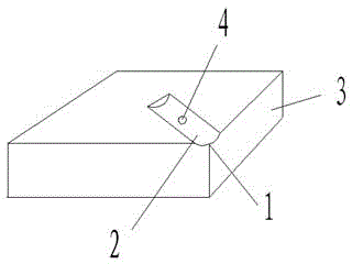
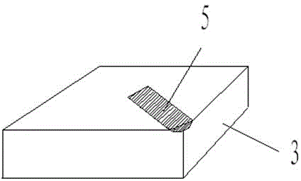
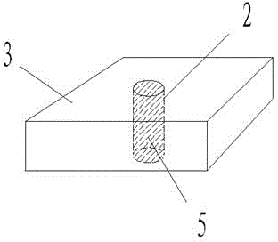
[0014] Embodiment of the present invention: a method for blocking the glue inlet and the glue flow path of the mold. When the glue inlet and the glue flow path of the mold are blocked, the fitter drills the material nest on the glue flow path in advance, and then Then press the rivet into the glue inlet and the glue flow channel, and the fitter uses tools to beat and squeeze the rivet, so that the rivet can be filled and firmly attached to the glue inlet and the glue flow channel, and then the glue inlet and the glue flow channel are fixed. The end and the surface of the glue flow channel are smoothed to ensure that the filling part and the surface of the mold are smooth and flat, and the filling of the glue inlet hole and the glue flow path can be completed.

[0015] The rivets are aluminum ri...


PUM

PropertyMeasurementUnit
depthaaaaaaaaaa

Abstract

The invention discloses a method and a structure for plugging a glue inlet hole and a glue channel of a mould. The method includes the steps of 1) pre-drilling a material cave on the glue channel by a bench worker when the glue inlet hole and the glue channel of the mould need to plug; 2) pressing a rivet into the glue inlet hole and the glue channel and striking and extruding the rivet by the bench worker with tools so that the rivet fully fills and is firmly attached to the glue inlet hole and the glue channel; and 3) sleeking the two ends of the glue inlet hole and the surface of the glue channel to ensure the filled position and the surface of the mould to be smooth and flat to finishing plugging of the glue inlet hole and the glue channel. The structure is simple, safe and reliable, is smart in design and simple in operation, is free of build-up welding by a welder and reduces process turnover and process turnover time. The plugging material after improvement is aluminum which is easier to repair when compared with a build-up welding material, so that fitting time of a bench worker is reduced. The method is increased by 300-400% in efficiency after improvement.

Description

technical field [0001] The invention relates to a method for plugging a glue inlet hole and a glue flow path of a mold, and belongs to the technical field of mold transformation. Background technique [0002] At present, when many molds are producing and processing parts, the glue inlet and flow channel used before need to be changed. In this way, the original glue inlet and glue channel need to be blocked and repaired, and some mold cavities are thinner and welded Sometimes due to local high heat, the cavity will be deformed or the template will be broken down, which will affect the use of the mold. [0003] There are two ways to block the glue inlet and flow path of the existing mold. The first is to use welding to block. Since the parting surface of the joint mold is mostly sharp edges, the heat dissipation speed of the sharp edges is slow during welding repair. , which will melt the sharp edge to cause undercut and expand the welding area, which will often cause serious...

Claims


Application Information

Patent Timeline
Patent Type & Authority Applications(China)
IPC IPC(8): B29C33/00B29C33/70
Inventor 徐晓峰顾丽华
Owner GUIZHOU GUIHANG AUTOMOTIVE COMPONENTS
Why Eureka
Try Eureka