
Structure formed by multiple parts

A technology of components and incisions, which is applied in the field of structures composed of multiple components, and can solve problems such as lengthening of time

Inactive Publication Date: 2016-02-10
GM GLOBAL TECH OPERATIONS LLC
View PDF7 Cites 7 Cited by
  • Summary
  • Abstract
  • Description
  • Claims
  • Application Information

AI Technical Summary

Problems solved by technology

The known method is time-consuming, energy- and material-intensive, since the tools necessary for heating the parts to be joined have to be prepared and produced, and the time spent for assembling the body is extended by at least as much as required for controlling the temperature of the components. time

Method used


Image

  • Structure formed by multiple parts
  • Structure formed by multiple parts
  • Structure formed by multiple parts

Examples


Embodiment Construction

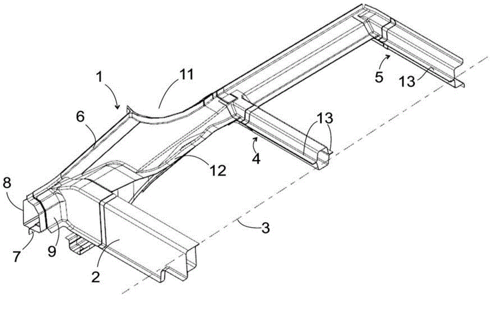
[0030] As the first usage example of the present invention, figure 1 Indicates a part that forms a frame structure of an automobile body. This frame structure comprises, in a known manner, a side member 1 which extends substantially along the entire length of the vehicle body, only its rear part being shown here, which extends from the footrest 2 in the direction of the rear of the vehicle. This frame structure is relative to figure 1 The plane of symmetry represented by the dotted line 3 is mirror-symmetrical; the half foot shelf 2 extending on the plane of symmetry and the crossbeams 4, 5 starting from the longitudinal beam 1 are not shown in the figure.

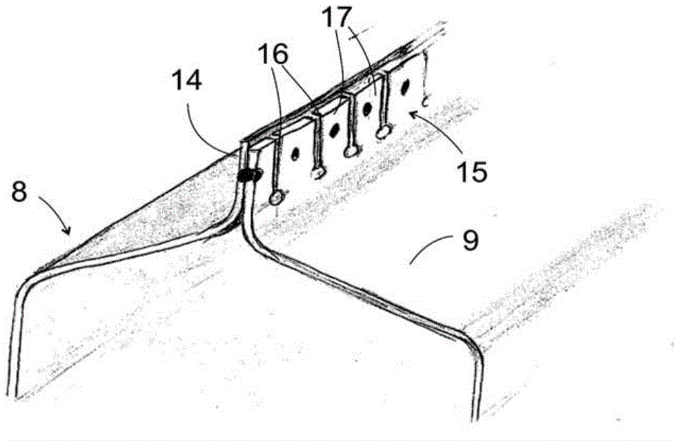
[0031] The side member 1 consists of several thin plates, which are connected to one another in overlapping areas extending in the longitudinal direction of the vehicle, for which purpose long flanges formed on the edges of the thin plates are welded, glued or fixed to one another. 8 or 9 designate two such sheets in the...


PUM


Abstract

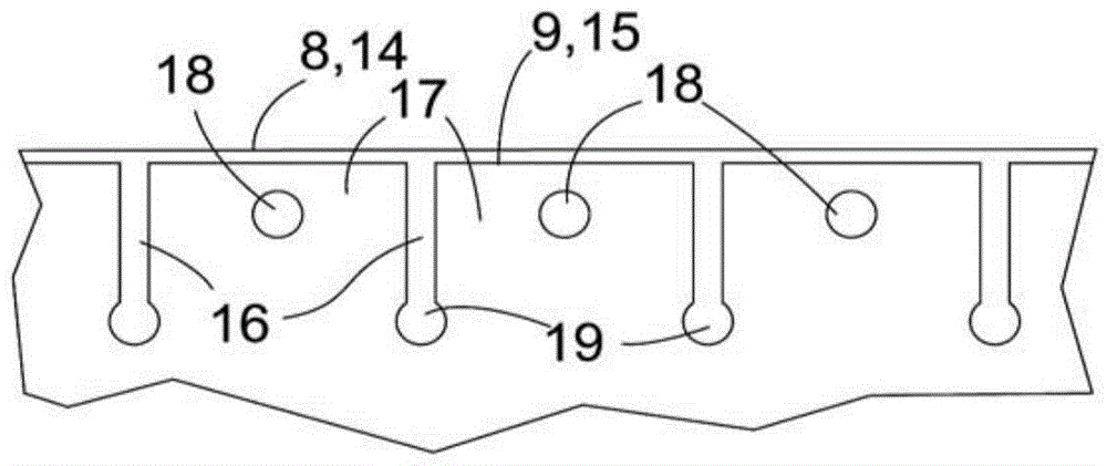
The invention relates to a structure, especially a vehicle body. The structure includes at least two components (21, 22) made from materials with different heat expansion coefficients and fastened to one another on an elongated overlap zone. The overlap zone on at least one first component (21) is subdivided by weak points (16) oriented in its transverse direction into portions (17) following one another in longitudinal direction.

Description

technical field [0001] The invention relates to a multi-component structure, in particular a motor vehicle body. Background technique [0002] In an effort to reduce the weight of the car body without compromising the static load capacity and the associated passenger safety, more possibilities have been investigated in recent years for car construction, combining different materials within the car body. A particularly difficult problem in this connection is thermal stresses, which can arise during temperature changes between components made of different materials and fixedly connected to each other at several points spaced apart from one another. [0003] Known by DE102011107035A1 is a method of combining components with different thermal expansion coefficients. According to this method, the components are preheated to the temperature of the midpoint of a temperature range. The two boundaries of put the structure in a state of stress, but these stresses are not so great tha...

Claims


Application Information

Patent Timeline
IPC IPC(8): B62D27/02
CPCB62D25/02B62D25/06B62D27/02B62D27/023F16B11/00
Inventor M.兰格
Owner GM GLOBAL TECH OPERATIONS LLC
Learn More