
Double-steel-plate concrete composite shear wall with U-shaped pull rods arranged in staggered mode

A combined shear wall, staggered arrangement technology, applied in the direction of walls, building components, buildings, etc., can solve the problems of large welding deformation, tedious bolt perforation operation, etc., achieve small shear slip, simple and easy installation process, The effect of large contact area

Inactive Publication Date: 2021-07-13
BEIJING UNIV OF TECH
View PDF12 Cites 0 Cited by
  • Summary
  • Abstract
  • Description
  • Claims
  • Application Information

AI Technical Summary

Problems solved by technology

[0005] Aiming at the deficiencies of the prior art, the present invention provides a double-steel plate concrete composite shear wall with staggered arrangement of U-shaped tie rods, which is mainly used to solve the large welding deformation and cumbersome bolt perforation operation existing in the composite wall using the traditional tie method. and other technical issues

Method used


Image

  • Double-steel-plate concrete composite shear wall with U-shaped pull rods arranged in staggered mode
  • Double-steel-plate concrete composite shear wall with U-shaped pull rods arranged in staggered mode
  • Double-steel-plate concrete composite shear wall with U-shaped pull rods arranged in staggered mode

Examples


Embodiment Construction

[0024] Below in conjunction with accompanying drawing and embodiment the present invention is described in further detail:

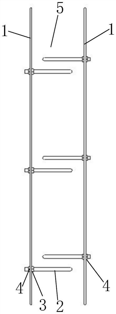
[0025] Such as Figure 1 to Figure 6 As shown, the double steel plate concrete composite shear wall with staggered arrangement of U-shaped tie rods mainly includes steel plates with openings on both sides (1), U-shaped tie rods (2), internal positioning nuts (3), external fixing nuts (4), and filled concrete (5).

[0026] The steel plate (1) with holes on both sides is processed on the basis of the flat steel plate to pass through the U-shaped tie rod. The diameter of the hole is determined according to the diameter of the tie rod, and there should be a gap of no more than 2mm after the tie rod passes through.

[0027] The raw materials of the U-shaped tie rods (2) are metal products with good ductility such as steel bars, screws, steel rods, etc., which are U-shaped by cold working. The clear distance between the U-shaped two limbs should be not less...


PUM


Abstract

The invention discloses a double-steel-plate concrete composite shear wall with U-shaped pull rods arranged in a staggered mode, and belongs to the technical field of civil engineering composite structures. The double-steel-plate concrete composite shear wall is mainly used for solving the problems of large welding deformation of external steel plates, difficulty in controlling welding residual stress, complexity in bolt perforation and the like in the prior art. The double-steel-plate concrete composite shear wall with the U-shaped pull rods arranged in the staggered mode is mainly composed of steel plates with holes in the two sides, the U-shaped pull rods, internal positioning nuts, external fixing nuts and filling concrete, wherein the U-shaped pull rods are metal products with good ductility such as a rebar, a screw rod, a steel bar and is in a U shape through cold machining, the end parts of the U-shaped pull rods are provided with threads capable of installing a bolt, and the U-shaped pull rods at adjacent positions of the steel plates on the two sides are staggered. Bolt connection is adopted, a large amount of welding work is avoided, welding deformation and welding residual stress do not exist, the outer steel plate can keep higher flatness, the staggered pull rods are large in contact area with concrete and small in shearing slippage, certain constraint can be provided for filling of the concrete, and the cooperative work capacity of the steel plates and the concrete is improved.

Description

technical field [0001] The invention relates to a double steel plate concrete composite shear wall, in particular to a double steel plate concrete composite shear wall with U-shaped tie rods staggered, and belongs to the technical field of civil engineering composite structures. Background technique [0002] With my country's economic development and the continuous improvement of structural seismic performance requirements, double steel plate concrete composite shear wall structures are more and more used in nuclear power projects, offshore projects and high-rise buildings. As a new type of structure, the double steel plate concrete composite shear wall has the advantages of high bearing capacity, good seismic performance and simple construction compared with the traditional reinforced concrete shear wall. This structural form meets the requirements for the development of prefabricated buildings, is convenient for standardized design, factory processing, and on-site assembly...

Claims


Application Information

Patent Timeline
Patent Type & Authority Applications(China)
IPC IPC(8): E04B2/00E04B2/56
CPCE04B2/00E04B2/56
Inventor 李振宝赵玉坤马华
Owner BEIJING UNIV OF TECH
Learn More