Integrated liquid rocket engine thrust chamber top cover structure

A liquid rocket and engine technology, applied in the mechanical field, can solve the problems of increasing the risk of ignition gas burning through the outlet pipe, increasing the structural weight, etc., to avoid welding deformation and welding stress, increase installation space, and reduce weight.

Active Publication Date: 2022-04-29
BEIJING AEROSPACE PROPULSION INST
View PDF4 Cites 0 Cited by
  • Summary
  • Abstract
  • Description
  • Claims
  • Application Information

AI Technical Summary

Problems solved by technology

In this case, due to the limited space in the center area of ​​the top cover, the igniter of the thrust chamber is generally arranged outside the top cover, and the ignition gas is introduced into the thrust chamber through the gas outlet pipe, which not only increases the structural weight, but also increases the ignition gas. Risk of burning through the outlet tube

Method used


Image

  • Integrated liquid rocket engine thrust chamber top cover structure
  • Integrated liquid rocket engine thrust chamber top cover structure
  • Integrated liquid rocket engine thrust chamber top cover structure

Examples


Embodiment Construction

[0028] In order to better understand the above technical solutions, the technical solutions of the present application will be described in detail below through the accompanying drawings and specific examples. It should be understood that the embodiments of the present application and the specific features in the examples are detailed descriptions of the technical solutions of the present application, and It is not a limitation to the technical solutions of the present application, and the embodiments of the present application and the technical features in the embodiments can be combined without conflict.

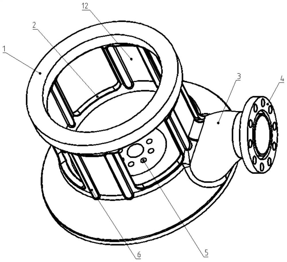
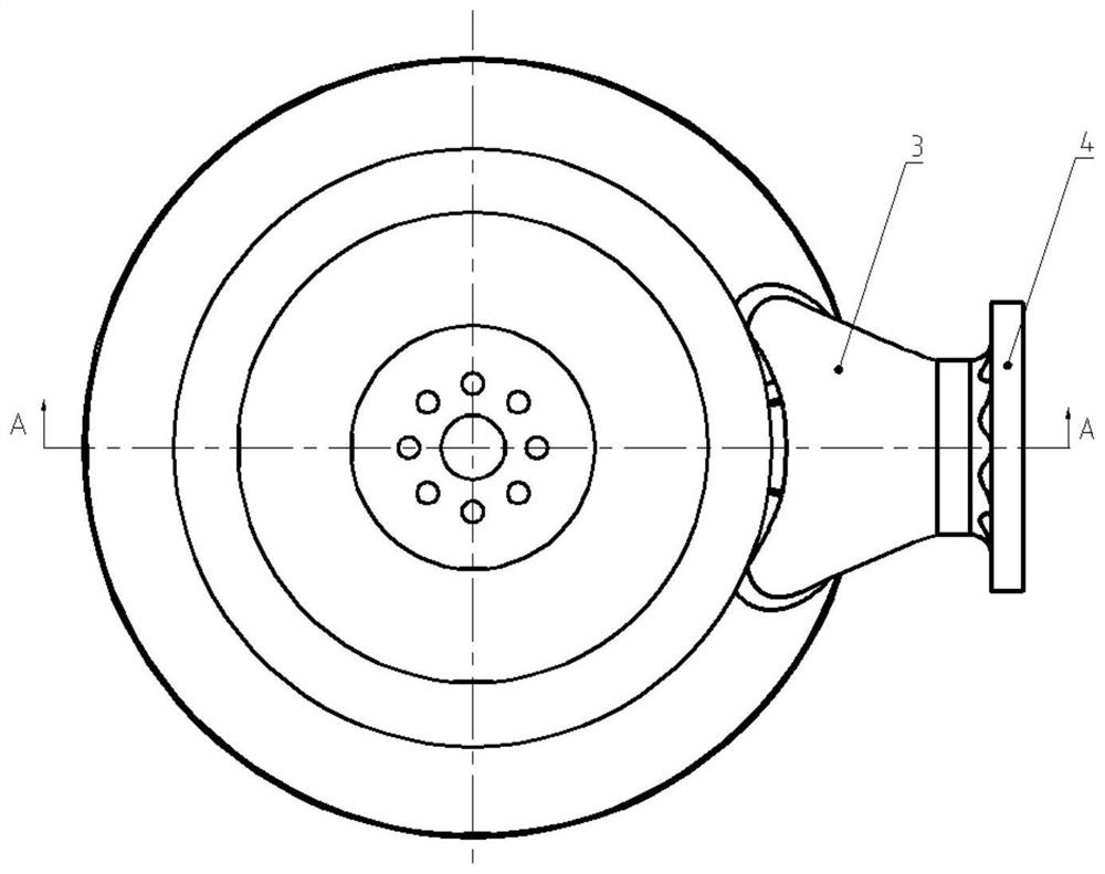
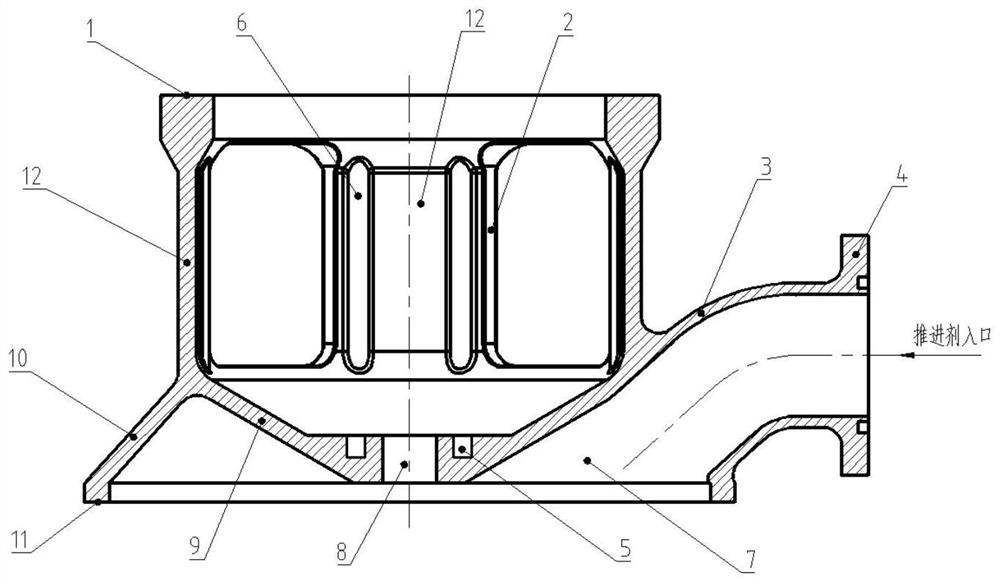
[0029] A kind of integrated liquid rocket engine thrust chamber roof structure provided by the embodiment of the present application will be described in further detail below in conjunction with the accompanying drawings, and the specific implementation methods may include (such as Figure 1~3 Shown): propellant inlet flange 4, propellant inlet elbow 3, inner cone surface 9...


PUM


Abstract

The invention discloses an integrated liquid rocket engine thrust chamber top cover structure, and belongs to the technical field of machinery. The top cover comprises a force bearing end face, a propellant inlet bent pipe, a propellant inlet flange, a top cover inner cavity, an inner conical surface, an outer conical surface, a top cover bottom surface and a force bearing wall. Thrust generated by a thrust chamber of the liquid rocket engine is transmitted to the top cover from the bottom face of the top cover, transmitted to the force bearing wall through a triangular force bearing structure formed by the inner conical face and the outer conical face and finally transmitted to an engine rack through the force bearing end face. Propellant enters the top cover from a propellant inlet in the propellant inlet flange, flows through the propellant inlet bent pipe, enters the inner cavity of the top cover and then enters the downstream nozzle.

Description

technical field [0001] The invention relates to a top cover structure of an integrated liquid rocket engine thrust chamber, belonging to the technical field of machinery. Background technique [0002] The traditional liquid rocket engine top cover is generally used to form a propellant liquid collection chamber with inlet flanges and equalizer parts. In order to make the outlet flow of the thrust chamber nozzle uniform, it is necessary to install structures such as a flow equalizer inside the top cover to reduce the total pressure distortion in the liquid collection chamber and increase the structural weight. In addition, for rocket engines using non-pyrophoric propellants, an igniter needs to be provided to ignite and start the thrust chamber. Therefore, above the top cover, it is necessary to weld structures such as load-bearing seats and support plates to be connected with the engine frame to increase the installation space of the igniter. This design has high requireme...

Claims


Application Information

Patent Timeline
Patent Type & Authority Applications(China)
IPC IPC(8): F02K9/62F02K9/44
CPCF02K9/62F02K9/44
Inventor 孔维鹏谢恒刘倩潘刚张亚韩长霖潘亮刘红珍张晋博
Owner BEIJING AEROSPACE PROPULSION INST
Why Eureka
Try Eureka