
a synchronous brake

A technology of brakes and brake ropes, applied in the field of synchronous brakes, which can solve the problems of inconvenient operation of the speed control handle, use of the front brake alone or first, tail flicking or forward turning, etc., to achieve large braking force, light brake, The effect of short reaction times

Active Publication Date: 2018-06-19
南通市通州区同博机械制造有限公司
View PDF5 Cites 0 Cited by
  • Summary
  • Abstract
  • Description
  • Claims
  • Application Information

AI Technical Summary

Problems solved by technology

Existing brakes all adopt two handbrakes that are contained on the cross tube of the front of the car to control the front and rear brakes respectively. When some people ride a bicycle, they do not hold the handlebars, and some fingers rest on the handbrake handles, which is not safe. It is also inconvenient to operate the speed control handlebars. Some people hold the handlebars, and it is too late to grasp the handbrake handles in an emergency. Wearing gloves in winter and sweating hands in summer, these problems are more obvious
There is also the problem of the order of using the front and rear handbrakes. Although the manufacturer emphasizes in the vehicle manual that the front brakes are not allowed to be used alone or first, otherwise the car will flick or turn forward when the speed is fast. After all, this is the responsibility of the car brake itself. Technical defects, it is not enough to point out in the instruction manual

Method used


Image

  • a synchronous brake
  • a synchronous brake

Examples


Embodiment Construction

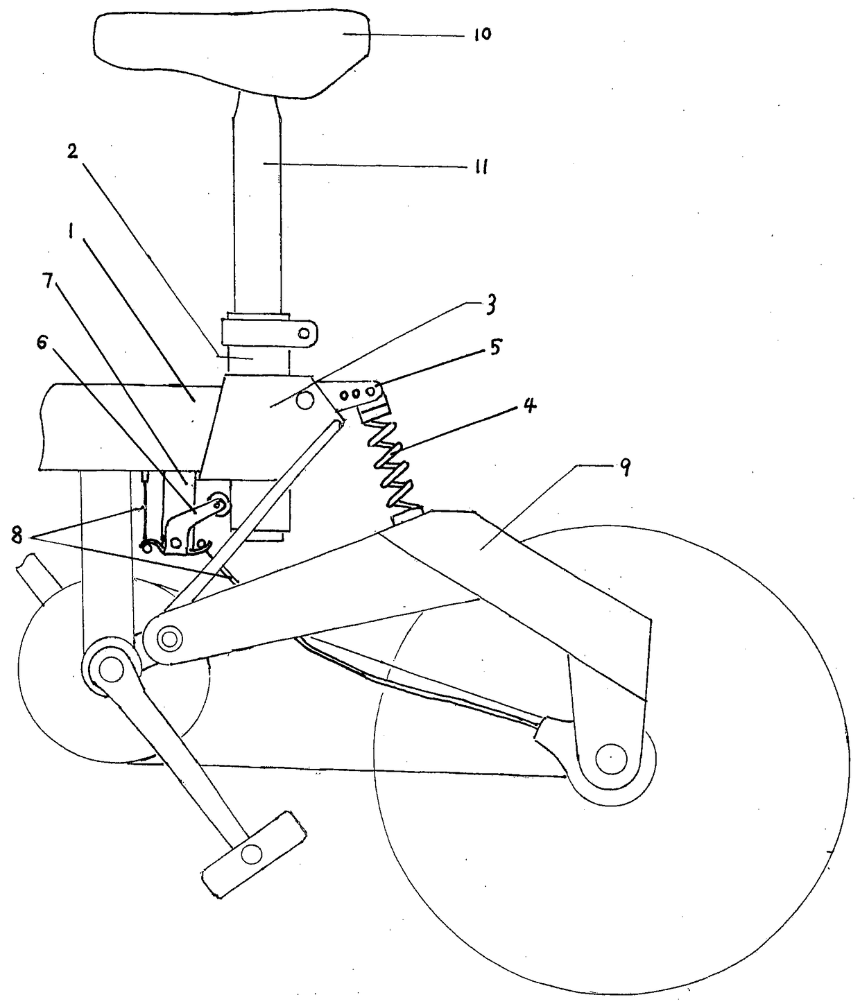
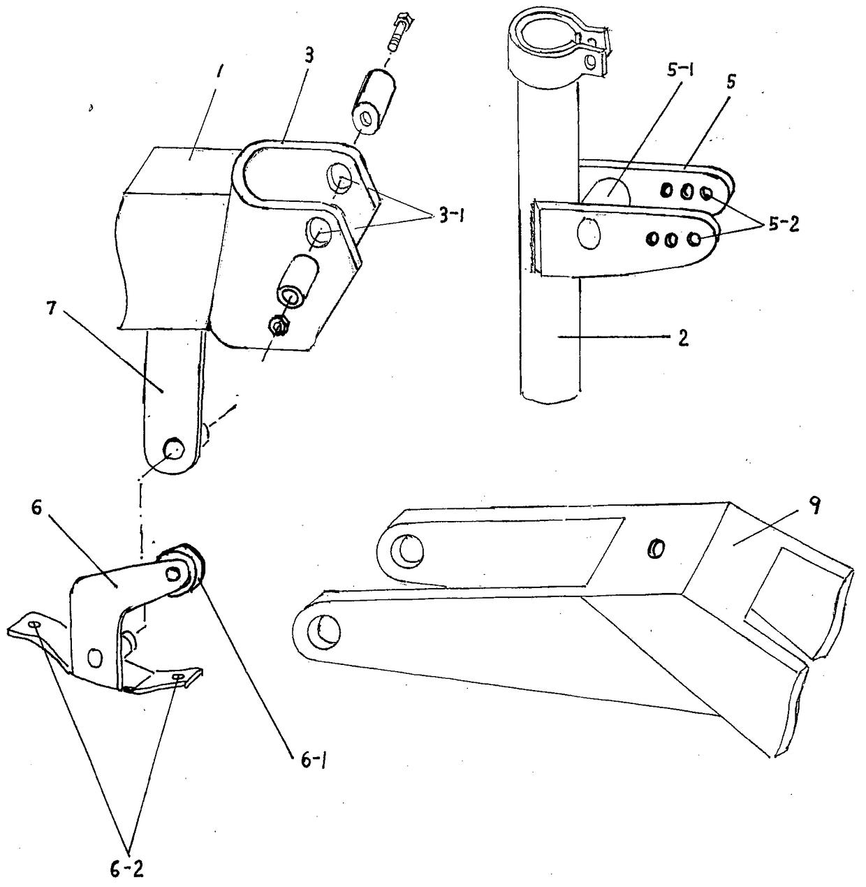
[0014] Embodiments of the present invention are as follows, the U-shaped support 3 is welded on the vehicle frame beam 1 earlier, and after the rear standpipe 2 is contained on the U-shaped support (3), the damping spring 4 is installed again, and at this moment, the top of the rear standpipe 2 It should be close to the rear edge of the upper opening of the U-shaped bracket 3. The roller 6-1 of the brake rope pull plate 6 should be in contact with the rear standpipe 2. Pull the rear standpipe 2 to make it rotate clockwise, and it should be able to push the brake rope to pull Plate 6 rotates counterclockwise, and pulls two brake ropes 8 that are passed in the hole 6-2 to make the front and rear brakes brake. The stability of the rear standpipe 2 can be adjusted by the elastic force of the shock absorbing spring 4, or can be adjusted by selecting the mounting hole 5-2 on the upper end of the shock absorbing spring 4, or by increasing or decreasing the axle sleeve 5-1 and the rear...


PUM


Abstract

The invention provides a synchronous brake which serves as a device for controlling a brake, and belongs to the technical field of two-wheel carts and three-wheel carts. Brakes of existing two-wheel carts and three-wheel carts are installed on transverse tubes of handlebars, the two hands need to not only hold the handlebar but also perform braking, the right hand also needs to regulate the speed when some carts are driven, control is very uncomfortable and the safety is also affected, and especially when the cart speed is high, the risk of tail drifting or front turning can occur if braking is performed by only using a front brake or by using the front brake firstly and then using a back brake. According to the synchronous brake, a brake rope pulling plate is pushed by a cart back stand tube which can rotate backwards to synchronously pull a front brake rope and a back brake rope to brake the cart, the hands can truly hold the handlebar, the front wheel and the back wheels are synchronously braked, the cart is attractive and tidy, and the safety performance is good.

Description

technical field [0001] The invention relates to a synchronous vehicle brake, which is used for synchronously operating the brakes of the front wheels and rear wheels of two-wheel vehicles and tricycles, and belongs to the technical field of two-wheel vehicles and three-wheel vehicles. Background technique [0002] Existing two-wheel vehicles, because of their convenience, economy and environmental protection, have been used by more and more people, but the number of traffic accidents produced by them is also very large, in addition to road conditions, congestion, failure to obey traffic rules and In addition to riding technical problems, the technical defects of the brake itself are also an important reason. Existing brakes all adopt two handbrakes that are contained on the cross tube of the front of the car to control the front and rear brakes respectively. When some people ride a bicycle, they do not hold the handlebars, and some fingers rest on the handbrake handles, whic...

Claims


Application Information

Patent Timeline
Patent Type & Authority Patents(China)
IPC IPC(8): B62L3/08B62K5/02
Inventor 王民海
Owner 南通市通州区同博机械制造有限公司
Learn More