A vehicle clutch assembly with sliding fuel saving function

A clutch and clutch shaft technology, which is applied to vehicle components, control devices, transportation and packaging, etc., can solve the problems of not meeting the needs of the maximum driving torque of the vehicle, not suitable for the vehicle to save fuel for a long time, and the maximum torque is limited. It is convenient for product promotion and application, reliable locking and small transmission torque.

Inactive Publication Date: 2016-04-06
ANYANG INST OF TECH
View PDF8 Cites 0 Cited by
  • Summary
  • Abstract
  • Description
  • Claims
  • Application Information

AI Technical Summary

Problems solved by technology

However, the existing glider invention adopts direct manual control, or adopts pneumatic power or electromagnetic power, and locks the active and driven parts of the overrunning clutch through the engagement sleeve, which is not only inconvenient to operate, but also takes a long time to lock, and even requires Parking to operate the locking controls is one of the main reasons why taxis are not widely used
To solve this problem, the patent application number is 200920313828.7 and the authorized announcement number is CN201554791U, which adopts the guide structure with inclined planes in the inner teeth of the ring gear. Although the meshing speed is improved to a certain extent, it still cannot satisfy the safety that the locking should be synchronized with the wheel braking. Requirements, and part of the engaging tooth is cut off, which reduces the strength of the tooth and affects the service life
[0005] Third, the existing slider is installed between the transmission output shaft and the drive shaft, or between the drive axle half shaft and the wheel hub, which not only causes the odometer Ineffective, and after the deceleration and torque increase of the transmission, the transmitted torque increases, and the force on the parts increases. At the same time, the space of the installation part is limited, which limits the size of each component part, resulting in an increase in failure rate and reduced work reliability; and sliding The working environment of the slider is poor, the vibration is large, and the joint between the driving and driven parts will produce a large impact during acceleration, etc., all of which affect the service life of the slider and limit the wide application of slider technology by automobile manufacturers.
[0006]Modern automobiles use electronically controlled clutches and electromagnetic clutches, and the ECU controls the clutch engagement or separation, which can cut off the power transmission between the engine and the transmission in a timely manner, improving the degree of automation , which reduces the driver's operating intensity and can improve the fuel-saving effect during coasting; however, the electromagnetic clutch maintains the engaged state by electromagnetic force, and consumes electric energy all the time when engaged, which affects the overall fuel-saving effect, and the maximum torque it transmits is limited. It cannot meet the needs of the maximum driving torque of the vehicle; the electronically controlled clutch uses the ECU to control the motor, and realizes the control of the clutch through the motor. Due to the long reaction time of the motor, and the fact that the motor is always energized and the release bearing is always in the running state during the clutch separation process, the electronically controlled The clutch is also not suitable for frequent long-term fuel-saving coasting of the vehicle

Method used


Image

  • A vehicle clutch assembly with sliding fuel saving function
  • A vehicle clutch assembly with sliding fuel saving function

Examples


Embodiment Construction

[0026] The following is a specific embodiment of the present invention, and further describes the technical solution of the present invention in conjunction with the accompanying drawings, but the present invention is not limited to this embodiment.

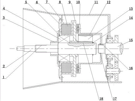
[0027] Such as figure 1 As shown, the clutch assembly housing of the present invention is integrated with the transmission housing, and the main parts include: housing 11, clutch shaft 2, electromagnetic clutch suction disc 7, driving disc 9, driven disc 10, overrunning clutch 13, Clutch shaft bearing 4, transmission input shaft 15 and other components. The spline 1 at the front of the clutch shaft is used to install the driven disc of the traditional dry friction disc clutch, and the rear part of the clutch shaft is connected with the driving disc 9 of the electromagnetic clutch and the active part of the overrunning clutch through the flat key 18—the inner ring, the overrunning clutch The driven part of the outer ring is ...


PUM


Abstract

The invention provides a vehicle clutch assembly with a sliding fuel-saving function; the device is composed of a starting clutch, a free sliding clutch and a lock-up clutch, the starting clutch is connected in series with the free sliding clutch, and the free sliding clutch is connected in parallel with the locking clutch; The starting clutch adopts a dry friction plate clutch, which is installed at the front of the clutch shaft. The free-slip clutch adopts a low secondary overrunning clutch, which is installed at the rear of the clutch shaft together with the lock-up clutch; the lock-up clutch adopts an electromagnetic clutch, controlled by a brake switch. It is jointly controlled with the electromagnetic clutch switch, quickly locks the free-sliding clutch, and realizes the synchronization of engine braking and wheel braking; the invention reduces vehicle fuel consumption, reduces engine wear, reduces the driver's work intensity, and improves driving safety; Reasonably combine products with mature technology and reliable quality to generate new functions, significantly reduce costs, improve product reliability, and lay the foundation for wide application of products.

Description

technical field [0001] The invention relates to the technical field of automobiles, in particular to an automobile clutch and an energy-saving sliding device. Background technique [0002] Due to its reliable technology, mature technology, and low cost, automotive manual transmissions will still be widely used at present and in the future for a period of time; traditional automotive clutches are dry friction plate clutches, which are devices that connect the engine and transmission. It is divided into engagement mode and disengagement mode, and its working state affects the energy consumption of the vehicle; during the driving process of the car, there is often sliding movement. The inertial energy produced in the engine is wasted in vain because the engine is dragged backwards, which not only increases fuel consumption, but also aggravates the pollution of the automobile exhaust to the environment. Some experienced drivers, when the vehicle is coasting, cut off the connect...

Claims


Application Information

Patent Timeline
Patent Type & Authority Patents(China)
IPC IPC(8): B60K17/02B60K23/02
Inventor 王俊昌李军民王飞王晓晶师会超
Owner ANYANG INST OF TECH
Why Eureka
Try Eureka