Conveying device for steel members

A technology of conveying device and steel components, which is applied to conveyors, transportation and packaging, etc., can solve the problems of inability to adjust, cannot realize transmission in the same production line, and small size range of steel pipe transmission, and achieves the effect of improving versatility

Inactive Publication Date: 2016-02-10
SHANGHAI BAOSTEEL IND TECHNOLOGICAL SERVICE
View PDF8 Cites 7 Cited by
  • Summary
  • Abstract
  • Description
  • Claims
  • Application Information

AI Technical Summary

Problems solved by technology

[0002] All kinds of steel components need to be conveyed during the production process. Various steel components such as steel pipes, steel plates, strip steel, etc., such as steel pipe conveying equipment in steel pipe production plants, the steel pipe transmission components are fixed on the frame, and the steel pipes are located on the The transmission is realized on the transmission component. Since the transmission component is a fixed structure and is fixedly connected to the frame, it can only transport steel pipes of a certain size. For steel pipes that are too large or too small, the same production line transmission cannot be realized; the traditional transportation The equipment cannot be adjusted according to the size of the steel pipe, the size range of the steel pipe transmission is small, and the versatility is poor

Method used


Image

  • Conveying device for steel members
  • Conveying device for steel members
  • Conveying device for steel members

Examples


Embodiment Construction

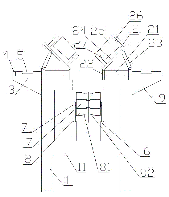
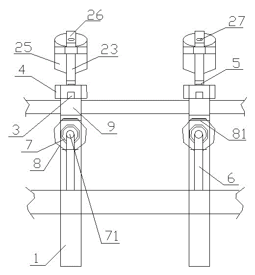
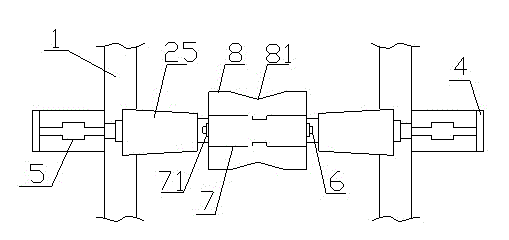
[0015] like figure 1 , figure 2 and image 3 As shown, the conveying device for steel components of the present invention includes a frame 1, the top surface of which is open and a crossbeam 11 is provided at the bottom of the frame 1, and the device also includes a transmission assembly 2, a guide rail 3, a baffle plate 4, and a telescopic pull rod 5 , a telescopic support rod 6, a conveying roller 7 and a conveying belt 8, the guide rail 3 is arranged on both sides of the opening on the top surface of the frame 1 and extends to the outside of the frame 1, and the baffle plate 4 is arranged on the frame 1. The end of the guide rail 3 on the outside of the top surface. The transmission assembly 2 includes a base 21, a short pole 22, a long pole 23, a support frame 24 and a guide wheel 25. The base 21 is arranged on the guide rail 3 and runs along the guide rail. 3 moves, the bottom end of the short pole 22 is arranged on the inner side of the base 21, the bottom end of the ...


PUM


Abstract

The invention discloses a conveying device for steel members. Guide rails of the device are arranged on two sides of an opening in the top surface of a rack; baffles are arranged on outer sides of the top surface of the rack; bases are arranged on the guide rails and can move along the guide rails; bottom ends of short supporting rods are arranged on inner sides of the bases, bottom ends of long supporting rods are hinged to outer sides of the bases, top ends of the short supporting rods and top ends of the long supporting rods are hinged to bottom surfaces of supporting frames; guide wheels are arranged on the top surface of the supporting frames through shaft seats and wheel axles, a telescopic pull rod is arranged between each baffle and the corresponding base; telescopic supporting rods are arranged on the top surface of a cross beam at the lower part of the rack in a spaced manner; conveying rollers are arranged at top ends of the adjacent telescopic supporting rods through wheel axles and located below the opening in the top surface of the rack; conveying belts wind around the surfaces of the conveying rollers. The conveying device overcomes defects of traditional conveying equipment, can be adjusted according to the type and the size of the steel members during conveying and meets conveying requirements of the steel members, and the conveying universality of the steel members is improved.

Description

technical field [0001] The invention relates to a conveying device for steel components. Background technique [0002] All kinds of steel components need to be conveyed during the production process. Various steel components such as steel pipes, steel plates, strip steel, etc., such as steel pipe conveying equipment in steel pipe production plants, the steel pipe transmission components are fixed on the frame, and the steel pipes are located on the The transmission is realized on the transmission component. Since the transmission component is a fixed structure and is fixedly connected with the frame, it can only transport steel pipes of a certain size. For steel pipes that are too large or too small, the same production line transmission cannot be realized; the traditional transportation The equipment cannot be adjusted according to the size of the steel pipe, and the size range of the steel pipe transmission is small and the versatility is poor. Contents of the invention ...

Claims


Application Information

Patent Timeline
Patent Type & Authority Applications(China)
IPC IPC(8): B65G15/08B65G15/26
Inventor 项允
Owner SHANGHAI BAOSTEEL IND TECHNOLOGICAL SERVICE
Why Eureka
Try Eureka