Part conveying device for engineering machinery production and machining

A technology of construction machinery and conveying device

Active Publication Date: 2021-01-26
重庆云峰达机械制造有限公司
View PDF17 Cites 2 Cited by
  • Summary
  • Abstract
  • Description
  • Claims
  • Application Information

AI Technical Summary

Problems solved by technology

[0005] The object of the present invention is to provide a parts conveying device for construction machinery production and processing, to solve the problem of Since the traditional conveying device is often fixed, it can only complete the conveying between fixed heights, so that its height or inclination angle cannot be changed according to the transportation requirements of the parts and products, thus reducing the practicality of the parts conveying device

Method used


Image

  • Part conveying device for engineering machinery production and machining
  • Part conveying device for engineering machinery production and machining
  • Part conveying device for engineering machinery production and machining

Examples


Embodiment 1

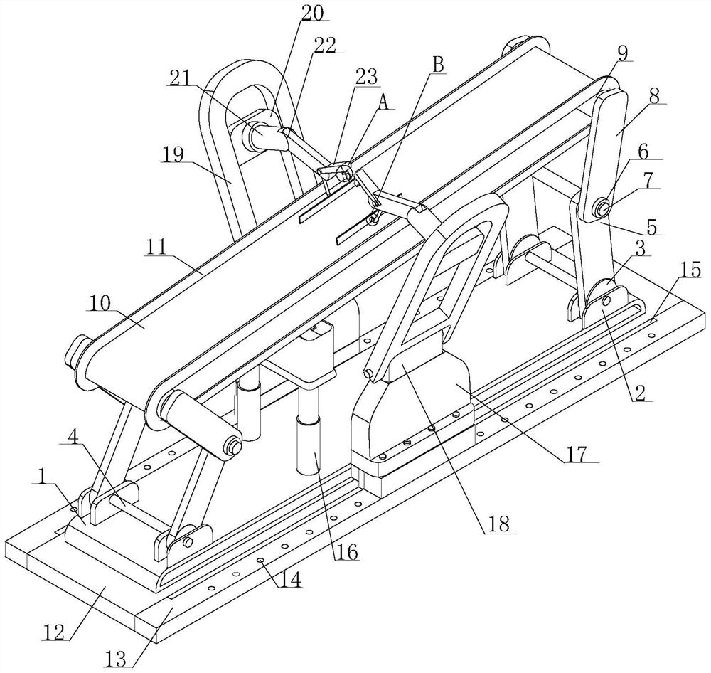
[0041] see figure 1 , the present invention provides a technical solution: a parts conveying device for construction machinery production and processing, including a support platform 1, a limiting plate 2 is arranged on the top of the supporting platform 1, and a rotating plate 3 is movably connected to the inner wall of the limiting plate 2. The inside of the plate 3 is provided with a linkage shaft-4, the outer wall of the linkage shaft-4 is fixedly connected with the inner wall of the rotating plate 3, and the outer wall of the end of the rotating plate 3 away from the support table 1 is fixedly connected with the adjusting plate-5, and one end of the adjusting plate-5 Fixedly connected with the outer wall of the rotating plate 3, the other end of the adjusting plate one 5 is provided with a linkage shaft two 7, and the two ends of the linkage shaft two 7 are flexibly connected with the inner wall of the adjusting plate one 5.

[0042] The outer wall of the linkage shaft 2 ...

Embodiment 2

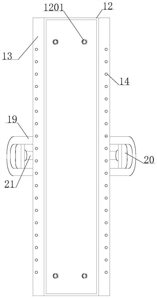
[0045] see Figure 1-7 , the present invention provides a technical solution: the bottom of the support platform 1 is provided with an installation base 12, the top of the installation base 12 is fixedly connected with the bottom of the support platform 1, the bottom of the installation base 12 is provided with a shock absorbing spring 1201, and the shock absorbing spring 1201 Fixedly installed on the inner wall of the mounting base 12, the two ends of the mounting base 12 are fixedly connected with a fixed table 13, the outer wall of the fixed table 13 is provided with a threaded hole 14, and the end of the threaded hole 14 near the mounting base 12 is provided with a chute 15, The chute 15 is opened on the top of the fixed platform 13; the top of the fixed platform 13 is movably equipped with a driving device 17, and the inside of the driving device 17 includes a support block 1701, and the bottom of the support block 1701 is provided with a connecting plate 1702, and one end...

Embodiment 3

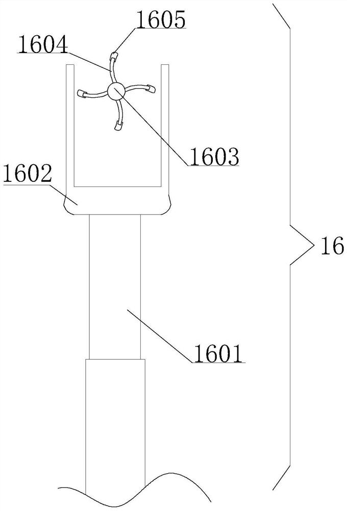
[0048] see Figure 1-5 , the present invention provides a technical solution: the top of the driving device 17 is fixedly mounted with a hinged block 18, the inner wall of the hinged block 18 is movably connected with a hinged rod, the two ends of the hinged rod are fixedly mounted with an adjustment frame 19, and the inside of the adjustment frame 19 is set There is a mounting plate 20, the outer wall of the mounting plate 20 is flexibly connected with the inwall of the adjusting frame 19, the outer wall of the mounting plate 20 is fixedly installed with a mounting seat, and the inwall of the mounting seat is fixedly equipped with a fixed rod 21; the fixed rod 21 is arranged away from one end of the mounting seat Movable rod 22 is arranged, and one end of movable rod 22 is movably connected with the inwall of fixed rod 21, and the other end inwall of movable rod 22 is movably connected with rotary knob, and the outer wall of rotary knob is fixedly equipped with adjusting colum...


PUM


Abstract

The invention discloses a part conveying device for engineering machinery production and machining, and belongs to the technical field of machining. The part conveying device for the engineering machinery production and machining comprises a supporting table, a limiting plate is arranged at the top of the supporting table, a rotating plate is movably connected to the inner wall of the limiting plate, the outer wall of a first linkage shaft is fixedly connected to the inner wall of the rotating plate, a first adjusting plate is fixedly connected to the outer wall of the end, away from the supporting table, of the rotating plate, one end of the first adjusting plate is fixedly connected with the outer wall of the rotating plate, a second linkage shaft is arranged at the other end of the first adjusting plate, the two ends of the second linkage shaft are movably connected to the inner wall of the first adjusting plate, the inner wall of the limiting ring is movably connected with the outer wall of the second linkage shaft, the height and the inclination angle of a transmission wheel can be adjusted by changing the angle between the first adjusting plate and a second adjusting plate, parts can be transported among different positions, the production efficiency is improved, and manpower resources are saved.

Description

technical field [0001] The invention belongs to the technical field of mechanical processing, and in particular relates to a parts conveying device for production and processing of engineering machinery. Background technique [0002] The production process of a machine refers to the entire process of making a product from raw materials (or semi-finished products). For machine production, it includes transportation and storage of raw materials, production preparation, blank manufacturing, processing and heat treatment of parts, product assembly, debugging, painting and packaging, etc. The content of the production process is very extensive. Modern enterprises use the principles and methods of systems engineering to organize and guide production, and regard the production process as a production system with input and output. [0003] In the production process, the process of changing the shape, size, position and nature of the production object to make it a finished or semi-f...

Claims


Application Information

Patent Timeline
Patent Type & Authority Applications(China)
IPC IPC(8): B65G41/00B65G47/22B65G47/252B65G45/10
CPCB65G41/005B65G47/22B65G47/252B65G45/10
Inventor 岑冠颖
Owner 重庆云峰达机械制造有限公司
Why Eureka
Try Eureka