
Digital printing machine with ink-jet printing beam

A technology of inkjet printing and printing machine, which is applied in the direction of printing and printing devices, and can solve the problems of non-fitting cylinders, bending of materials to be printed, and affecting the printing effect of materials, etc.

Inactive Publication Date: 2021-04-27
无锡市春阳印刷包装有限公司
View PDF0 Cites 0 Cited by
  • Summary
  • Abstract
  • Description
  • Claims
  • Application Information

AI Technical Summary

Problems solved by technology

[0004] Aiming at the deficiencies of the prior art, the present invention provides a digital printing machine for inkjet printing beams, which solves the problem that the traditional printing beam cylinders often do not adhere to each other due to mechanical errors and other factors when they are in use. The printing effect of the material, and when the material is conveyed between the two rollers, it is easy to appear that the edge of the material is against the surface of the roller, so that there is a problem of local bending of the material to be printed

Method used


Image

  • Digital printing machine with ink-jet printing beam
  • Digital printing machine with ink-jet printing beam

Examples


Embodiment

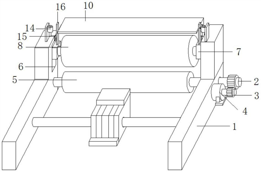
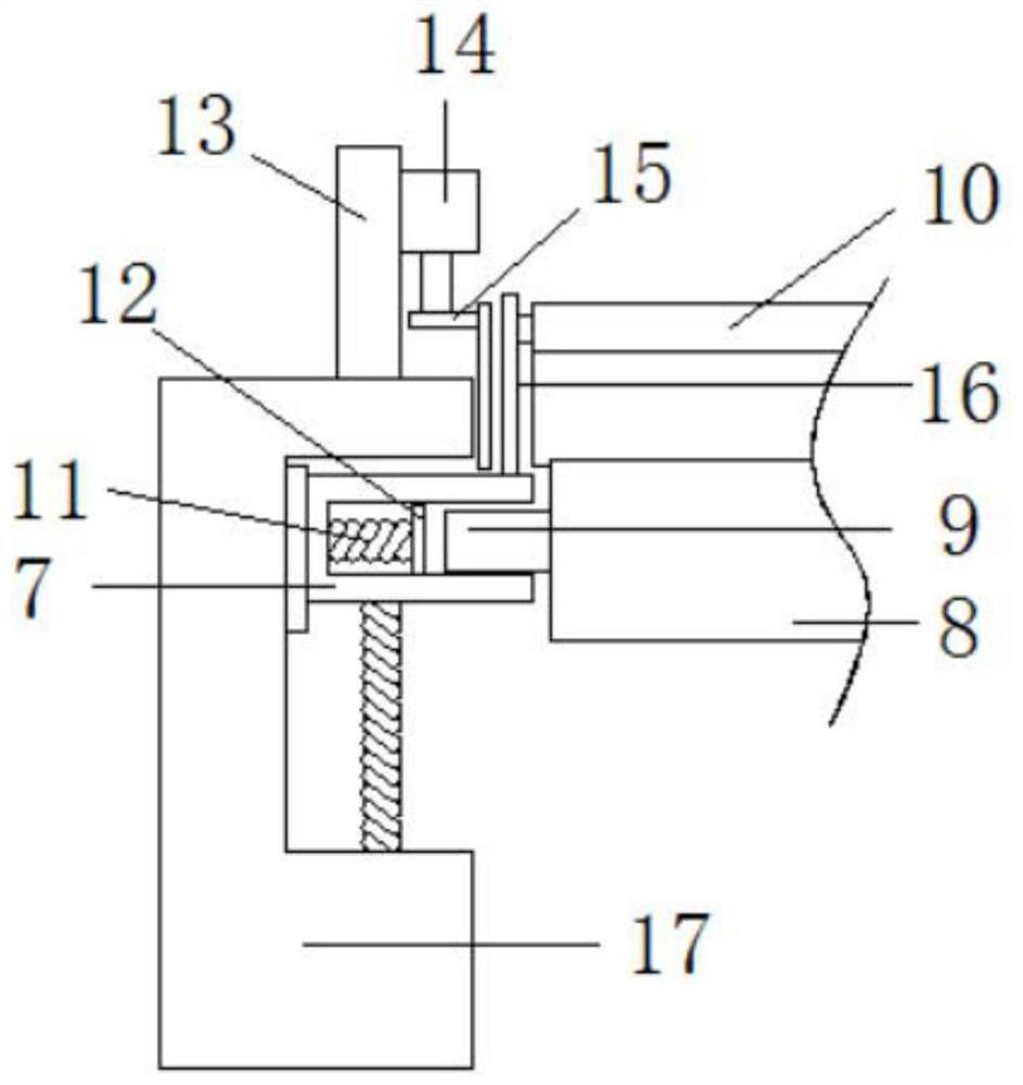
[0020] see Figure 1-2 , the present invention provides the following technical solutions: a digital printing machine for inkjet printing beams, including a frame 1, one end of the frame 1 is connected to the first cylinder 5 through a connecting shaft 2 in rotation, and one end of the connecting shaft 2 penetrates to the frame One side of the gear 1 is fixedly connected with a gear 3, and one side of the gear 3 is meshed with the output end of the motor 4 for transmission, and the motor 4 is fixedly connected to one side of the frame 1. A second cylinder 8 is movably connected between the two vertical plates 17, and the two ends of the second cylinder 8 are fixedly connected with a rotating shaft 9. The inner wall of the vertical plate 17 is provided with a chute 6, and the inside of the chute 6 is slidably connected with a slide block 7. , the inside of the slider 7 is provided with a blind hole for accommodating the rotating shaft 9, and the inside of the blind hole is elas...


PUM


Abstract

The invention relates to the technical field of printing machines, in particular to a digital printing machine with an ink-jet printing beam. The digital printing machine comprises a rack, wherein a first roller is rotatably connected to one end in the rack through a connecting shaft, one end of the connecting shaft penetrates to one side of the rack and is fixedly connected with a gear, one side of the gear is in meshing transmission with the output end of a motor, the motor is fixedly connected to one side of the rack, vertical plates are arranged at the front end of the top of the rack, and a second roller is movably connected between the two vertical plates. According to the digital printing machine, when materials are input, under the action of springs, sliding blocks are lifted to the highest end of a sliding groove, a gap between the second roller and the first roller is the largest, and the situation that the materials are bent due to contact with the second roller is avoided; the sliding blocks and the second roller are attached to the first roller, so that mechanical errors are avoided; and by adopting the design that the two ends of the second roller are embedded into the sliding blocks through rotating shafts and movable pieces are elastically connected into blind holes, the second roller and the sliding blocks can be conveniently and rapidly disassembled.

Description

technical field [0001] The invention relates to the technical field of printing machines, in particular to a digital printing machine for inkjet printing beams. Background technique [0002] A machine for printing text and images, a modern printing machine generally consists of mechanisms such as plate loading, ink application, embossing, and paper feeding. Its working principle is that the text and images to be printed are first made into a printing plate, installed on the printing machine, and then the ink is applied to the text and image on the printing plate manually or by the printing machine. [0003] In the process of using the printing machine, a corresponding roller is often added to the side of the printing beam of the printing machine, and then the surface of the material is sprayed and printed by the function of the roller. The function of the roller is to fit the surface of the material and prevent the surface of the material from lifting However, when the trad...

Claims


Application Information

Patent Timeline
Patent Type & Authority Applications(China)
IPC IPC(8): B41J11/00
CPCB41J11/0045
Inventor 华曙
Owner 无锡市春阳印刷包装有限公司
Learn More