This helps you quickly interpret patents by identifying the three key elements:
Problems solved by technology
Method used
Benefits of technology
Problems solved by technology
[0004] (1) The inevitable strong winds and waves in the ocean require that the safety factor of such power generation equipment and power plant buildings must be improved, so the initial investment cost increases;
[0005] (2) Seawater contains almost all elements in nature, so seawater constitutes an inevitable serious erosion of equipment, resulting in a greatly shortened expected service life of investment equipment, which is manifested in increased maintenance costs;
[0006] (3) In order to obtain the water source of the ocean surface or deep layer, it is not only extremely difficult to fix the pipeline at a depth of about 1,000 meters under the sea, but also has high risks and high costs, and the power consumption of the two high-power pumping systems takes up A large part of the system's power generation, so the power generation efficiency of the entire system is significantly reduced, which is reflected in the increase in unit electricity cost;
[0007] (4) Alternating seasons and lower sea surface temperature will make it difficult to maintain this power generation method. Although there are remedial ideas for combining solar energy and wind energy, they are not always effective. Therefore, the power generation efficiency of this type of power generation system in a year or in a day Large fluctuations and instability; if heat storage facilities are not considered, it may even cause intermittent or power outage events
[0008] Therefore, we clearly know that at home and abroad, there are actually power generation technologies that utilize low-grade ocean heat energy, power generation technologies that utilize factory waste heat in the range of 380-90 °C, and power generation technologies that utilize heat energy from high-temperature geothermal wells, etc., but So far, we have not heard about the practical application report of low-grade thermal power generation technology using inland river water or air, or "ultra-low temperature power generation technology"-the key problem is that when the inland normal temperature environment is used as a heat source, people can hardly find it. Cold water (4-5°C) at a sea depth of 1,000 meters is used as a suitable inland cold source for hot wells, and the technical means of ordinary condensers, which usually require a positive temperature gradient between the tail gas and hot wells, are here The environment is completely invalid, and the Rankine cycle system cannot be established. Therefore, for a long time, people have been unable to directly transplant low-grade thermal power generation technology from the ocean to the inland normal temperature environment.
Method used
Image
Click on the blue label to locate the original text in one second.
Reading with bidirectional positioning of images and text.
Examples
example 1
[0043] Example 1. Common scheme
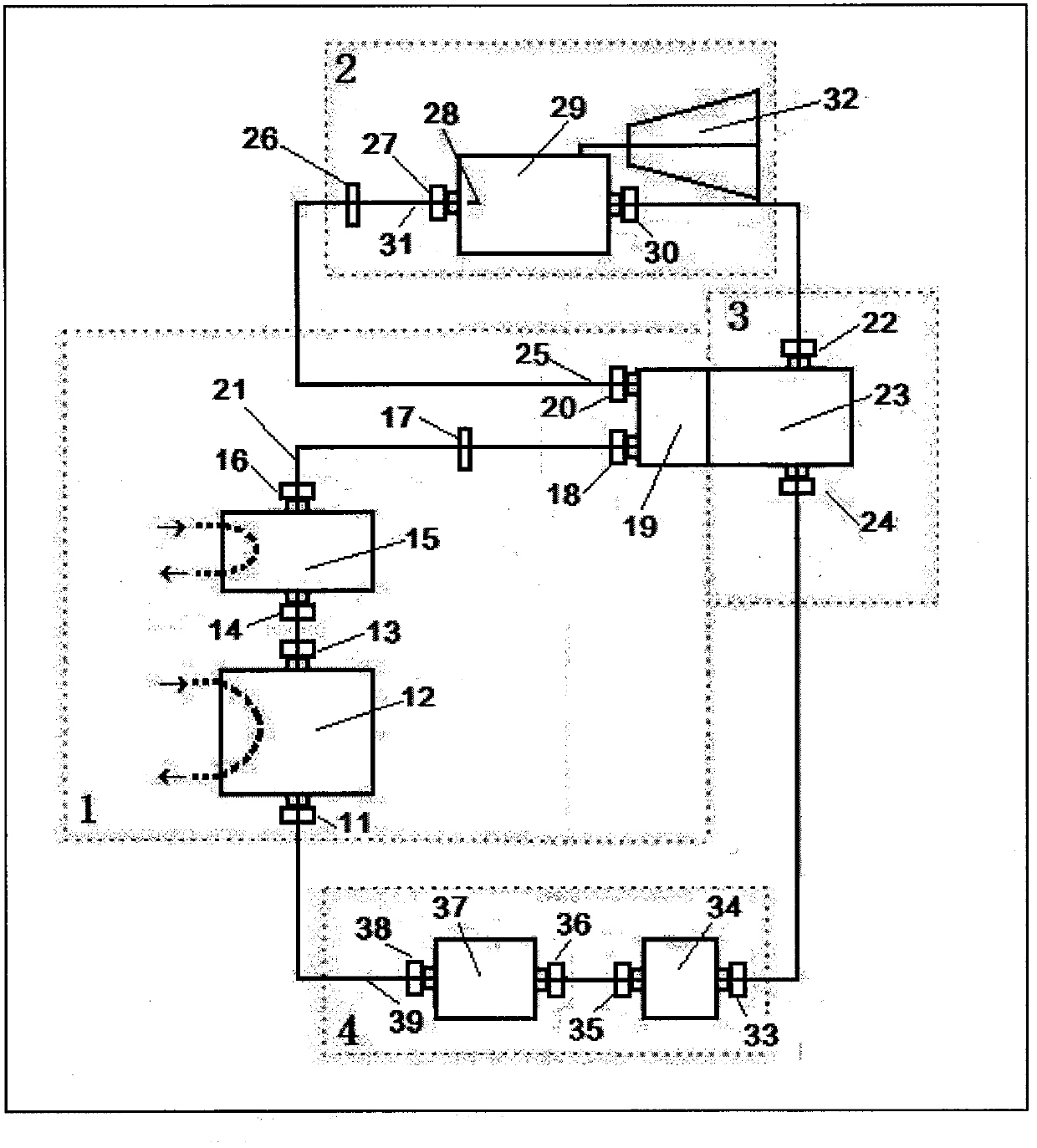
[0044] This scheme is suitable for general heat source occasions, including the use of natural environmental heat sources or man-made environmental heat sources, such as factory waste heat, and the water or gas of the heat source needs to be input into the gas-liquid phase heat exchanger through the pump or air pump, so it is called ordinary Type scheme.
[0045] The heat accumulation mechanism 1, the energy conversion mechanism 2, the cooling and liquefaction mechanism 3 and the working fluid circulation mechanism 4 are connected by pipelines in sequence. That is, the working medium inlet valve 11 of the liquid phase heat exchanger, the liquid phase heat exchanger 12, the working medium outlet valve 13 of the liquid phase heat exchanger, the working medium inlet valve 14 of the gas phase heat exchanger in the heat accumulation mechanism 1, and the gas phase heat exchanger 15. Gas-phase heat exchanger working medium outlet valve 16, first che...
example 2
[0049] Example 2. Energy-saving and high-efficiency solution
[0050] Compared with Example 1, this scheme is called energy-saving and high-efficiency type, because it does not need to pump water or air, which reduces the power consumption of water pumping or air pumping, so it is energy-saving and efficient. It is suitable for mountainous rivers with a water temperature above 30±10℃ all year round, with a certain water level gradient, or a certain flow rate, and is also suitable for outputting water flow or airflow in a factory waste heat type with a positioning difference and a certain pressure.
[0051] The system of this scheme is basically the same as Example 1, and the power generation mode is also the same, the difference is how to obtain the heat source water or gas process. In this scheme, the liquid phase heat exchanger 12 and the gas phase heat exchanger 16 are directly placed in the flowing river water, so the water (gas) on the heat exchange system side of the gas...
example 3
[0052] Example 3. Low-temperature photothermal water storage scheme
[0053] Compared with Example 1, this scheme is called low-temperature photothermal water storage type, because heat storage facilities and light field facilities are added to solve the heat source problem in areas with higher latitude and lower temperature. It is especially suitable for inland environments with long sunlight and unsatisfactory water sources, or marine or lake river environments with sufficient water sources but large temperature differences between day and night.
[0054] This scheme is basically the same as Example 1, and the power generation mode is also the same, the difference lies in the intervention and preparation for the external heat source. In this solution, the light field focusing mirror array uses sunlight to focus and heat the aqueous solution in the storage tank during the daytime. The aqueous solution in the storage tank is the heat source of the system. Generally, there are...
PUM
Abstract
The invention discloses a novel energy conversion system. The novel energy conversion system includes a heat aggregation mechanism, an energy conversion mechanism, a cooling and liquefying mechanism, and a working medium circulation mechanism which are connected in a pairwise manner. The whole system accords with the operating principle of the Rankine heat engine cycle system and the second law of thermodynamics. In the heat aggregation mechanism, a gas-liquid phase combined heat exchange component is used for technological aggregation and transfer of heat from a natural environmental heat source or an artificial environmental heat source to a working medium; in the cooling and liquefying mechanism, a forced type condenser technology is used to achieve effective heat dissipation and liquefaction of a working medium tail gas; in the working medium circulation mechanism, a working medium pump and a liquid storage tank are used to achieve the possibility of circulatory movements of the working medium in a closed system; in the energy conversion mechanism, an energy conversion assembly is used to convert the heat energy of working medium gas flows entering the mechanism into mechanical energy, or further convert the mechanical energy into electric energy. The energy conversion system provided by the invention is an improved and innovative energy conversion system, which can utilize energies, including but not limited to various low-grade heat energies, and convert the low-grade heat energies into mechanical power for work. The novel energy conversion system is a novel power generation system when connected with a power generator.
Description
Technical field: [0001] The invention relates to a novel energy conversion system. Background technique: [0002] With the shortage of energy resources in the world and the aggravation of environmental pollution, people pay attention to and realize how to develop and utilize the huge amount of low-grade heat energy that actually exists in natural space and waters. This low-grade thermal energy is essentially the heat given to the earth by solar radiation, so it is inexhaustible and inexhaustible, and it is the most green, clean, environmentally friendly and renewable cycle. At present, countries all over the world are investing and competing with each other, trying to gain a leading position in the field of developing and utilizing ocean low-grade thermal energy power generation technology, which greatly promotes the rapid development of ocean low-grade thermal energy power generation technology, making this power generation technology already commercially valuable . [00...
Claims
Application Information
Patent Timeline
Application Date:The date an application was filed.
Publication Date:The date a patent or application was officially published.
First Publication Date:The earliest publication date of a patent with the same application number.
Issue Date:Publication date of the patent grant document.
PCT Entry Date:The Entry date of PCT National Phase.
Estimated Expiry Date:The statutory expiry date of a patent right according to the Patent Law, and it is the longest term of protection that the patent right can achieve without the termination of the patent right due to other reasons(Term extension factor has been taken into account ).
Invalid Date:Actual expiry date is based on effective date or publication date of legal transaction data of invalid patent.

