
Circular charging battery integrated box capable of being rapidly replaced for new energy vehicle

A technology for rechargeable batteries and new energy vehicles, which is applied in the direction of secondary batteries, battery pack components, battery/battery traction, etc. It can solve the problems that only returning to the original factory can be replaced, and the battery cannot be replaced frequently, so as to achieve a solid structure Reliable, Powerful, and Simple to Connect

Inactive Publication Date: 2019-09-17
安徽姆大陆科技发展有限公司
View PDF0 Cites 0 Cited by
  • Summary
  • Abstract
  • Description
  • Claims
  • Application Information

AI Technical Summary

Problems solved by technology

[0002] Passenger cars have indeed made travel more convenient since they entered people's lives, but they have been powered by petroleum fuels. In order to save limited petroleum resources and protect the environment, human beings need more environmentally friendly energy to drive cars. At present, the easiest way to achieve it is electric energy. , New energy electric vehicles are gradually entering people's lives. At present, the battery boxes used by electric vehicles are fixed and can only be replaced by returning to the original factory; The existing charging methods must be parked at a fixed location for a long time to ensure normal use. The battery cannot be replaced frequently and removed for recharging.

Method used


Image

  • Circular charging battery integrated box capable of being rapidly replaced for new energy vehicle
  • Circular charging battery integrated box capable of being rapidly replaced for new energy vehicle
  • Circular charging battery integrated box capable of being rapidly replaced for new energy vehicle

Examples


Embodiment Construction

[0019] In order to make the implementation technical means, creative features, objectives and effects of the present invention easy to understand, the present invention will be further elaborated below in conjunction with specific illustrations.

[0020] like Figure 1-8 as shown,

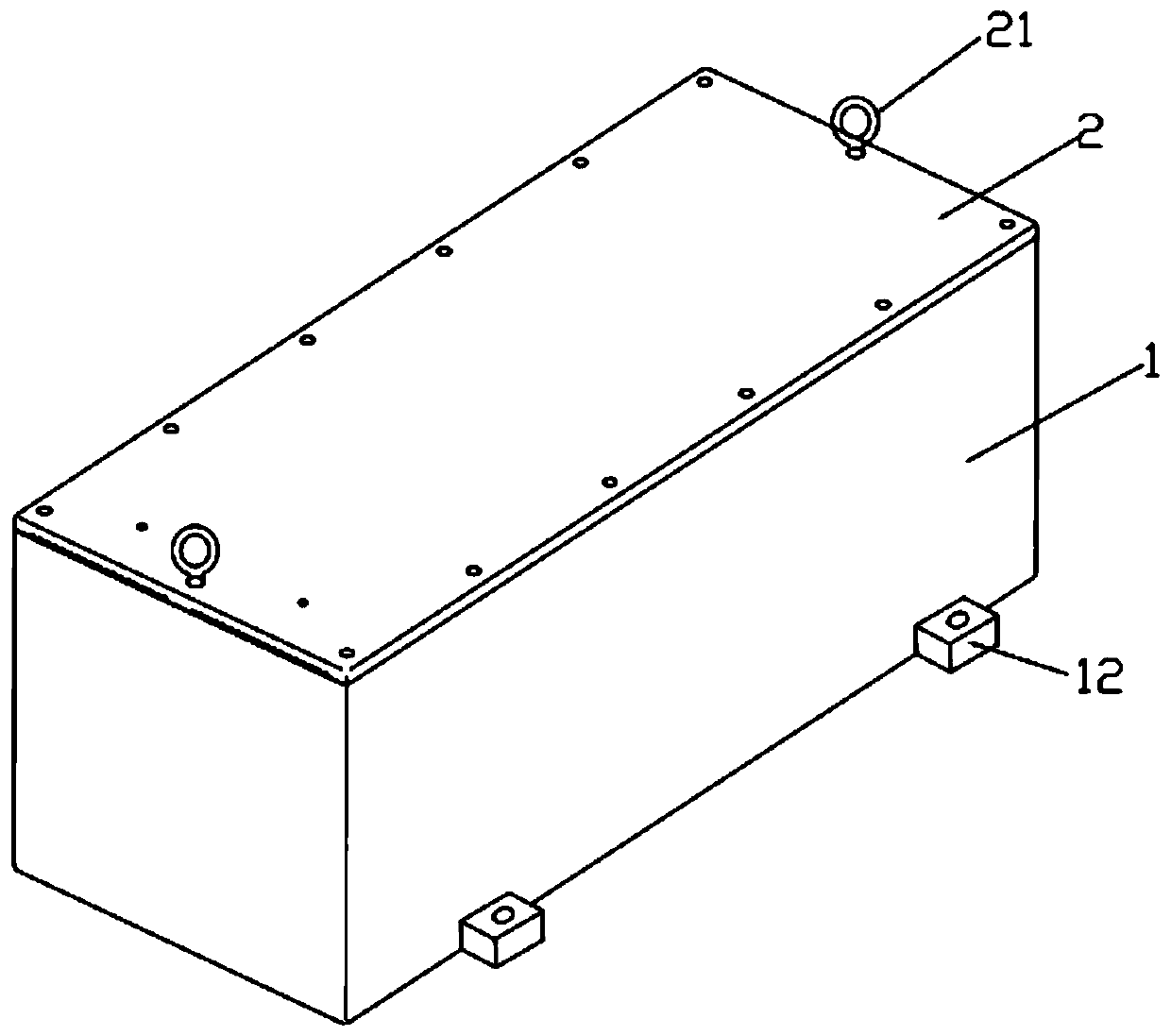
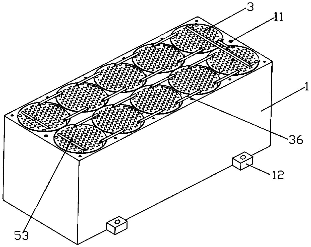
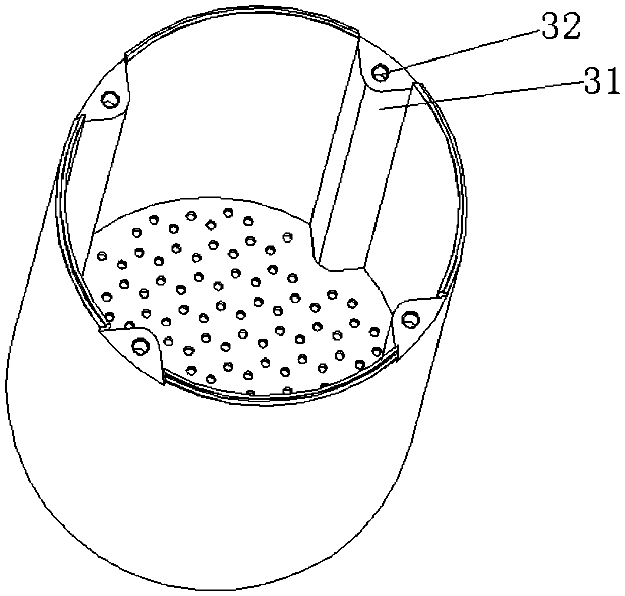
[0021] In this embodiment, a quick-change cycle rechargeable battery integrated box for new energy vehicles includes a rectangular combined box (1) and a sealed box cover (2) to cover the upper opening of the box (1), and the box (1) A number of cylindrical slots are arranged in the interior to place the battery barrel (3) embedded, and the first screw holes (11) are uniformly arranged around the edge of the box body (1), and the box cover (2) covers the combination box The upper end of the body (1) is fixedly connected with the internal thread of the first screw hole (11) through a bolt; the battery barrel (3) is stacked and assembled with several battery boxes (4), and the inner end wall of the ...


PUM


Abstract

The invention provides a circular charging battery integrated box capable of being rapidly replaced for a new energy vehicle. The circular charging battery integrated box comprises a rectangular combined case body and a sealing case cover covering an upper opening of the case body, and a plurality of cylindrical grooves are formed in the case body in an arrayed mode and used for placing battery barrels in an embedded mode. A battery case is firm and reliable in structure, connecting is easy, the electrifying ability is high, the occupied position is small, ventilation and heat dissipation can be effectively realized, thus temperature rising in use is relieved, heat dissipation holes can realize natural ventilation and heat dissipation, and copper tubes can also be used for centralized control over heat dissipation; the battery case is designed to be in a replaceable mode and can be replicated in batches to form the same standard of the battery case, a common crane can be established at an oil filling station to rapidly replace the battery case with the small electric amount with a fully charged battery case, the replacing time can be controlled within five minutes and is almost the refueling time, and through the replaceable mode of the battery case, the energy supplementing shortcoming of the new energy vehicle can be solved; and the replaced battery barrels can be circularly charged, and can be used circularly and repeatedly after being fully charged.

Description

technical field [0001] The invention relates to the technical field of new energy batteries, in particular to a quick-change cycle rechargeable battery integration box for new energy vehicles. Background technique [0002] Passenger cars have indeed made travel more convenient since they entered people's lives, but they have been powered by petroleum fuels. In order to save limited petroleum resources and protect the environment, human beings need more environmentally friendly energy to drive cars. At present, the easiest way to achieve it is electric energy. , New energy electric vehicles are gradually entering people's lives. At present, the battery boxes used by electric vehicles are fixed and can only be replaced by returning to the original factory; Existing charging methods must be parked at a fixed location for a long time to ensure normal use. The battery cannot be replaced frequently and taken down for recharging. [0003] Based on the above, we need a better techn...

Claims


Application Information

Patent Timeline
Patent Type & Authority Applications(China)
IPC IPC(8): B60L50/64B60L58/26H01M2/10H01M2/20H01M10/613H01M10/625H01M10/6562
CPCB60L50/64B60L58/26H01M10/613H01M10/625H01M10/6562H01M50/20H01M50/502Y02E60/10Y02T10/70
Inventor 朱广志
Owner 安徽姆大陆科技发展有限公司
Learn More