
a shunt

A shunt, current technology, applied in instruments, voltage/current isolation, measurement devices, etc., can solve the problems of low precision and high power consumption, and achieve the effect of small thermal volume, reduced use, and reduced power consumption

Inactive Publication Date: 2019-04-19
SHANXI XINGYONGMING INSTR
View PDF12 Cites 1 Cited by
  • Summary
  • Abstract
  • Description
  • Claims
  • Application Information

AI Technical Summary

Problems solved by technology

[0005] The technical problem to be solved by the present invention is to provide a low-power and high-precision shunt for the defects of high power consumption and low precision of the existing traditional shunt

Method used

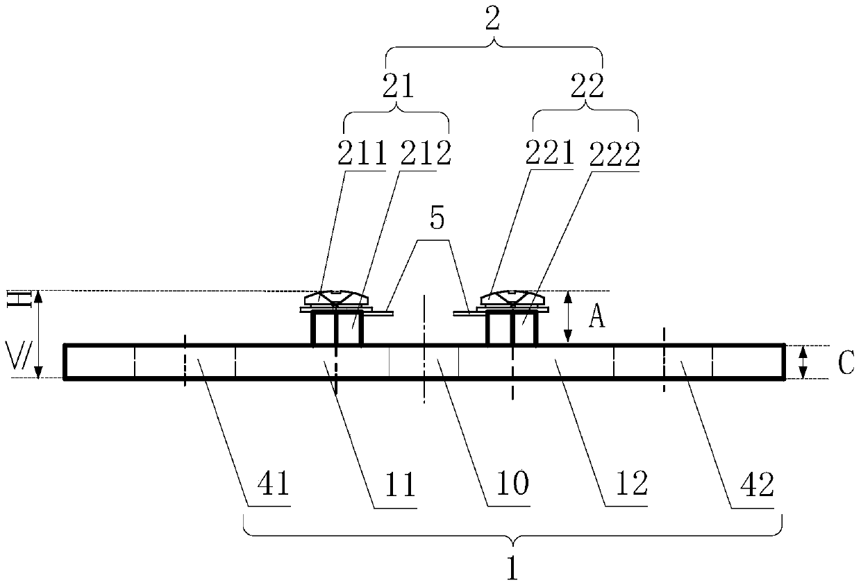
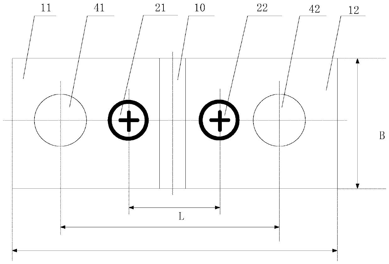
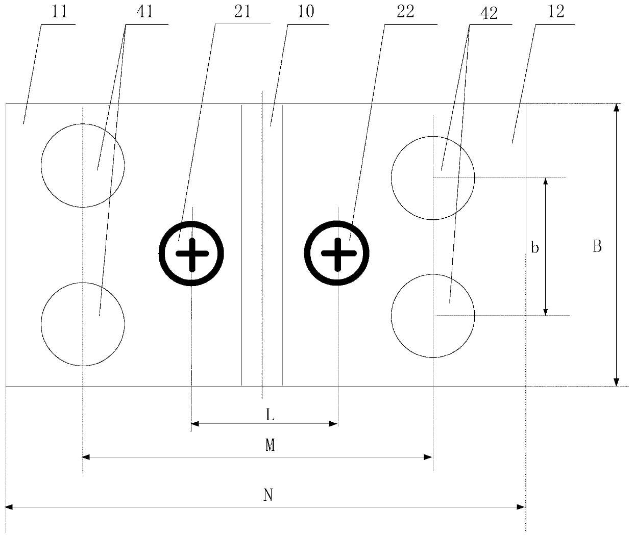

Image

  • a shunt
  • a shunt
  • a shunt

Examples


Embodiment Construction

[0026] In order to have a clearer understanding of the technical features, purposes and effects of the present invention, the specific implementation manners of the present invention will now be described in detail with reference to the accompanying drawings.

[0027] The main body of the shunt of the present invention adopts electron beam welding to combine the resistive material manganese copper plate and the conductive material red copper plate into one body, which not only utilizes the thermal stability of the manganese copper plate to ensure that the precision of the shunt when working meets the technical requirements, but also utilizes the excellent quality of copper. Conductivity is used to increase the accuracy of the shunt during measurement, thereby realizing a shunt with high precision and low power consumption.

[0028] figure 1 and figure 2 It is a schematic structural diagram of a flow divider according to an embodiment of the present invention. figure 1 main ...


PUM


Abstract

The invention relates to a shunt which comprises a shunt body and sampling columns. The shunt body comprises a manganese-copper plate in the center position and a first red copper plate and a second red copper plate which are symmetrically arranged at the two sides of the manganese-copper plate. The first red copper plate is provided with the first sampling column and at least one current input hole. The second red copper plate is provided with the second sampling column and at least one current output hole. The first red copper plate, the second red copper plate and the manganese-copper plate are identical in thickness and length, wherein the thickness is 2mm-12mm. Width of the manganese-copper plate is 5mm-15mm. Width of the first red copper plate and width of the second red copper plate are 40mm-60mm. The sum of the height of the sampling columns and thickness of the shunt body is not greater than H. The beneficial effects of the shunt are that the shunt formed by the red copper plates and the manganese-copper plate via welding has relatively-low sampling voltage, so that power consumption is greatly reduced; and meanwhile, sampling detection precision is enhanced through the sampling columns, and thus the domestic blank is filled.

Description

technical field [0001] The invention relates to the fields of communication equipment, instruments and meters, and electric appliance measurement and control, and more specifically relates to a shunt. Background technique [0002] The concept of the shunt comes from a resistance element connected in parallel when the instrument expands the range. In the DC circuit, it is connected in parallel with the magnetoelectric meter head of equal voltage to act as a current shunt to expand the range of the magnetoelectric ammeter. In recent years, with the rapid development of electronic industry and information technology, shunts have been widely used in communication systems, electronic complete machines, automation control and other fields, and play the role of current limiting, current sharing and sampling detection in equipment. [0003] The shunt is actually a high-power resistor. Due to the restriction of instrument technology in the early days, the voltage drop of the general ...

Claims


Application Information

Patent Timeline
Patent Type & Authority Patents(China)
IPC IPC(8): G01R15/00G01R15/14
Inventor 安梦学张玉明常福洪吴慧萍
Owner SHANXI XINGYONGMING INSTR
Learn More