Supercharge Your Innovation With Domain-Expert AI Agents!

Fuel cell stack

A fuel cell stack and fuel cell system technology, which is applied to fuel cells, fuel cell grouping, fuel cell additives, etc., can solve problems such as supercooling and performance degradation, and achieve the effects of small performance deviation and simplified manifold block structure.

Inactive Publication Date: 2016-02-10
HYUNDAI MOTOR CO LTD +1
View PDF7 Cites 3 Cited by
  • Summary
  • Abstract
  • Description
  • Claims
  • Application Information

AI Technical Summary

Problems solved by technology

In low temperature flood conditions, as opposed to high temperature conditions, the inlet cells of the cell stack can be supercooled so that the performance is quite degraded compared to the remote cells

Method used


Image

  • Fuel cell stack
  • Fuel cell stack
  • Fuel cell stack

Examples


Embodiment Construction

[0062] It should be understood that the term "vehicle" or "vehicle" or other similar terms as used herein includes motor vehicles, generally such as passenger vehicles including sport utility vehicles (SUVs), buses, trucks, various commercial vehicles, Vessels including boats and ships of all kinds, aircraft, and vehicles including hybrids, electric vehicles, plug-in hybrids, hydrogen vehicles and other alternative fuel vehicles (such as fuels from non-petroleum sources). As used herein, a hybrid vehicle is a vehicle that has two or more sources of power, such as gasoline-powered and electric-powered vehicles.

[0063] The present invention will now be described more fully hereinafter with reference to the accompanying drawings, in which exemplary embodiments of the invention are shown so that those skilled in the art may easily practice the invention. As those skilled in the art would realize, the described embodiments may be modified in various different ways, all without de...


PUM


Abstract

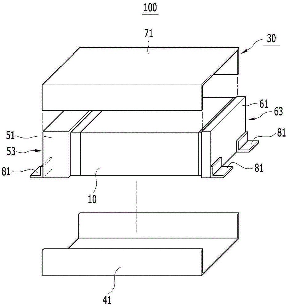
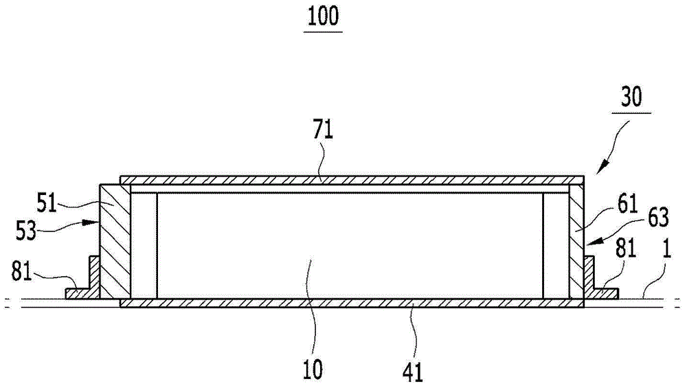
Disclosed herein is a fuel cell stack. The fuel cell stack includes: at least one unit stack comprising an assembly of unit cells and an enclosure protecting the unit stack. In particular, reaction gas inlet / outlet channels for supplying reaction gas to the unit stack are formed on a first side surface of the enclosure, and coolant inlet / outlet channels for supplying a coolant to the unit stack are formed on a second side surface of the enclosure.

Description

[0001] Cross References to Related Applications [0002] This application claims priority and benefit from Korean Patent Application No. 10-2014-0099205 filed with the Korean Intellectual Property Office on Aug. 1, 2014, the entire contents of which are incorporated herein by reference. technical field [0003] The present invention relates to fuel cell stacks. A fuel cell stack includes an assembled structure of unit stacks and packages. Background technique [0004] The fuel cell system generates electricity through the electrochemical reaction of hydrogen and oxygen and can be used in fuel cell vehicles. [0005] The fuel cell system includes a fuel cell stack, a hydrogen supply part that supplies hydrogen to the fuel cell stack, an air supply part that supplies air to the fuel cell stack, and a fuel cell stack configured to remove reaction heat and water from the fuel cell stack and condition the fuel cell stack. The temperature of the heat / water control unit. [0006...

Claims


Application Information

Patent Timeline
Patent Type & Authority Applications(China)
IPC IPC(8): H01M8/24H01M8/02
CPCH01M8/2475H01M8/04007H01M8/04089H01M2250/20Y02T90/40Y02E60/50Y02E60/10H01M8/02H01M8/04H01M50/20H01M8/24H01M8/2484H01M8/0267
Inventor 金德焕许容锡白硕玟
Owner HYUNDAI MOTOR CO LTD
Features
  • R&D
  • Intellectual Property
  • Life Sciences
  • Materials
  • Tech Scout
  • Unparalleled Data Quality
  • Higher Quality Content
  • 60% Fewer Hallucinations
Learn More