Working table for avoiding scattering of scraps in mechanical part machining process

A technology of mechanical parts and processing process, which is applied in the field of workbench to avoid the scattering of scraps during the processing of mechanical parts, and can solve the problems of inconvenient cleaning of scraps and scattering of scraps

Inactive Publication Date: 2016-02-17
LUZHOU YUANCHENG ENG MACHINERY CO LTD
View PDF5 Cites 16 Cited by
  • Summary
  • Abstract
  • Description
  • Claims
  • Application Information

AI Technical Summary

Problems solved by technology

[0004] The purpose of the present invention is to provide a workbench that avoids the scattering of scraps during the processing of mechanical parts, solves the problem of inconvenient cleaning of debris generated during the processing of mechanical parts in the prior art, and realizes convenient and fast cleaning of the processing of mechanical parts purpose of crumbs on table

Method used


Image

  • Working table for avoiding scattering of scraps in mechanical part machining process

Examples


Embodiment 1

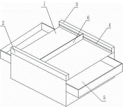
[0016] Such as figure 1 The shown workbench for avoiding the scattering of scraps during the machining of mechanical parts includes a square table body 1. The front and rear edges of the upper surface of the table body 1 are respectively provided with a vertical to the upper surface of the table body 1. No. 2 baffle 2, No. 2 baffle 3, the inner surface of the No. 1 baffle 2, the No. 2 baffle 3 is provided with a sliding groove 4 along the axial direction, and the sliding groove 4 is provided with a roller, The two rollers are connected by a scraper 6. The bottom 6 of the scraper is adjacent to the upper surface of the table body 1, and drawers 5 are provided on both the left and right sides of the table body 1. . In this embodiment, the two rollers are integrated with the scraper 6 fixed between the two rollers, and they can run along the chute 4 on the inner surface of the first baffle 2 and the second baffle 3. Since the bottom edge of the scraper 6 is adjacent to the upper...

Embodiment 2

[0018] Such as figure 1 On the basis of embodiment 1, the height of the scraper 6 and the first baffle 2 and the second baffle 3 are the same; Both ends of the sliding groove 4 are provided with stoppers. When processing mechanical parts in this embodiment, push the scraper 6 along the sliding groove 4 to the edge of the platform 1, and make it the same height as the No. 1 baffle 2, No. 2 The height of the baffle plate 3 is consistent, so as to prevent the scraper 6 from being too high to interfere with the actions of the operator and affect the processing of parts. After finishing a process, the scraper 6 is pushed to move it from one side of the table body 1 to the other side, so as to complete the cleaning of the surface of the table body 1. At the same time, the stoppers arranged at both ends of the sliding groove 4 can restrict the movement of the roller in the sliding groove 4, and prevent the user from sliding out of the sliding groove 4 and falling to the ground due t...


PUM


Abstract

The invention discloses a working table for avoiding scattering of scraps in the mechanical part machining process. The working table comprises a square table body, wherein a baffle plate No.1 and a baffle plate No.1 perpendicular to the upper surface of the table body are respectively arranged at the front edge and the rear edge of the upper surface of the table body; a sliding groove is formed in the inner surface of each of the baffle plate No.1 and the baffle plate No.1 on the axial direction, and a roller is arranged in each sliding groove; the two rollers are connected through a scratch board, and the bottom edge of the scratch board is adjacent to the upper surface of the table body; drawers are arranged in the left side surface and the right side surface of the table body. The working table solves the problem that scraps generated in the mechanical part machining process in the prior art is not conveniently swept and realizes the purpose of conveniently and quickly sweeping the scraps on the mechanical part machining working table.

Description

Technical field [0001] The invention relates to the field of parts processing devices, in particular to a workbench that avoids the scattering of waste debris during the processing of mechanical parts. Background technique [0002] Mechanical components, also known as mechanical components, are inseparable individual parts that make up machinery and machines. It is the basic unit of machinery, such as various bearings, valves, linkages, transmissions, and meshing devices. As early as before the advent of modern machinery, there were many prototypes of mechanical parts, but as a discipline, mechanical parts were separated from mechanical structure and mechanics. With the development of the machinery industry, the emergence of new design theories and methods, new materials, and new processes, mechanical parts have entered a new stage of development, and are now inseparable from people's daily lives. However, for mechanical parts, it must be processed on a machine tool or workbench...

Claims


Application Information

Patent Timeline
Patent Type & Authority Applications(China)
IPC IPC(8): B23Q1/25B23Q11/00B25H1/02
CPCB23Q1/25B23Q11/0042B25H1/02
Inventor 马赟
Owner LUZHOU YUANCHENG ENG MACHINERY CO LTD
Why Eureka
Try Eureka