Multifunctional cabinet door hinge

A multi-functional cabinet door technology, which is applied to hinges with pins, door/window accessories, construction, etc., can solve the problems of unstable opening and closing, small opening angle, and large gap between doors, so as to achieve easy opening and closing, The effect of large opening angle and small door gap

Inactive Publication Date: 2016-02-17
DONGGUAN SUOMAILUO METAL TECH CO LTD
View PDF6 Cites 9 Cited by
  • Summary
  • Abstract
  • Description
  • Claims
  • Application Information

AI Technical Summary

Problems solved by technology

[0002] At present, the traditional hinge is composed of connecting rods, pull rods, "pipe" racks, inner bases, outer door hinge cup seats and tension springs. Due to unreasonable structure and improper combination, it directly affects the use function of the hinge, and it is easy to appear after long-term use. In the case of failure to operate normally, the main focus is on the following points:
[0003] 1. Each component is easily damaged, the gap between the door gap is too large, the opening and closing swings, the offset sags, the service life is short, and it needs to be replaced frequently;
[0004] 2. When installing, it is necessary to drill holes in the door in advance. The installation positioning is limited, and it cannot be installed at will.
[0005] 3. When installing the full cover, half cover, and inner cover, it needs three models of straight bending, medium bending, and large bending to complete. The assembly is not simple, fast, easy, and inaccurate. The structure is not ideal and the practicability is deviated;
[0006] 4. The "pipe" frame is long, its bearing capacity is low, the working distance of the connecting rod and tie rod is short, the opening angle is small, it is inconvenient to use, and there are bad phenomena such as noise, looseness, deformation, and falling off when opening and closing

Method used


Image

  • Multifunctional cabinet door hinge
  • Multifunctional cabinet door hinge
  • Multifunctional cabinet door hinge

Examples


Embodiment Construction

[0022] The present invention will be described in further detail below in conjunction with the accompanying drawings.

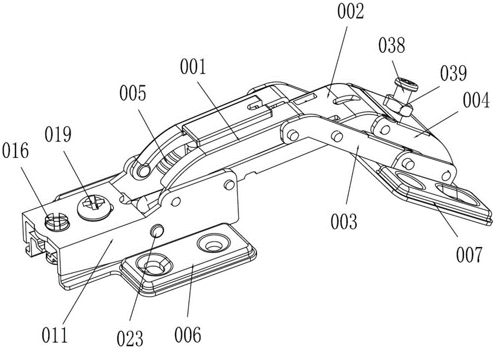
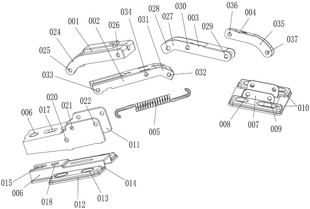
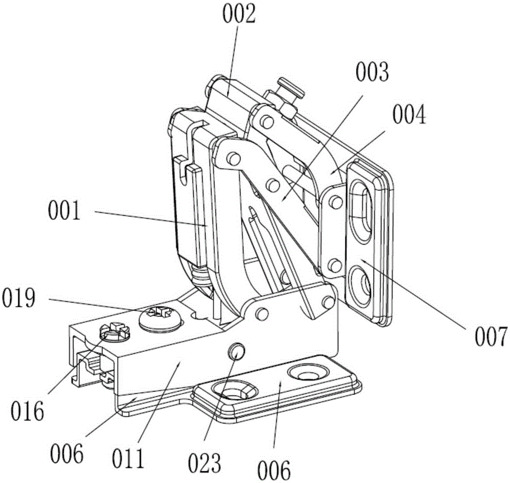
[0023] Figure 1 to Figure 3 A multifunctional cabinet door hinge according to the present invention is schematically shown.

[0024] For a multifunctional cabinet door hinge provided in this embodiment, please refer to Figure 1 to Figure 3 , including: main rotation rod 001, main rotation rod 002, transmission rod 003, transmission rod 004, tension spring 005, inner frame base 006 and outer door base 007, the outer door base 007 is provided with a second The ninth assembly hole 008 and the tenth assembly hole 009 are provided with second fixing holes 010 on the left and right sides of the outer door base 007, and an adjustable adjustment bracket 011 is provided on the inner frame base 006. The inner frame base 006 is provided with a first fixing block 012 extending to the left and right sides, the first fixing block 012 is provided with a first fixing hol...


PUM


Abstract

The invention discloses a multifunctional cabinet door hinge which comprises a main rotating pull rod, a main rotating connecting rod, a transmission connecting rod, a transmission pull rod, a tension spring, an inner frame base and an outer door base. An adjustable adjusting support is arranged on the inner frame base. The adjusting support is provided with a spring connecting hole. A first spring hook is arranged on the spring connecting hole. One end of the main rotating pull rod and one end of the main rotating connecting rod are connected with the adjusting support through shafts. The other end of the main rotating pull rod is connected with the transmission connecting rod, and the other end of the main rotating connecting rod is connected with the transmission pull rod. A first connecting hole is formed in the middle of the main rotating connecting rod. A second connecting hole is formed in the middle of the transmission connecting rod. The multifunctional cabinet door hinge is reasonable in structure, accurate, fast and easy to assemble, high in practicability and free of bad phenomena of noise, loosening, deformation, disengagement and the like during repeated starting.

Description

technical field [0001] The invention relates to the field of hardware components, in particular to an intelligent multifunctional cabinet door hinge. Background technique [0002] At present, the traditional hinge is composed of connecting rods, pull rods, "pipe" racks, inner bases, outer door hinge cup seats and tension springs. Due to unreasonable structure and improper combination, it directly affects the use function of the hinge, and it is easy to appear after long-term use. In the case of failure to operate normally, the main focus is on the following points: [0003] 1. Each component is easily damaged, the gap between the door gap is too large, the opening and closing swings, the offset sags, the service life is short, and it needs to be replaced frequently; [0004] 2. When installing, it is necessary to drill holes in the door in advance. The installation positioning is limited, and it cannot be installed at will. [0005] 3. When installing the full cover, half ...

Claims


Application Information

Patent Timeline
Patent Type & Authority Applications(China)
IPC IPC(8): E05F1/14E05D3/06E05D7/04E05D5/02E05D11/10
Inventor 罗日兴
Owner DONGGUAN SUOMAILUO METAL TECH CO LTD
Why Eureka
Try Eureka