Chain, chain coupler and connecting method of chain coupler
A coupling and chain technology, applied in the direction of belt/chain/gear, chain element, transmission chain, etc., can solve the problem of insufficient space for assembly and connection, and achieve the effect of ensuring strength and structural stability
- Summary
- Abstract
- Description
- Claims
- Application Information
AI Technical Summary
Problems solved by technology
Method used
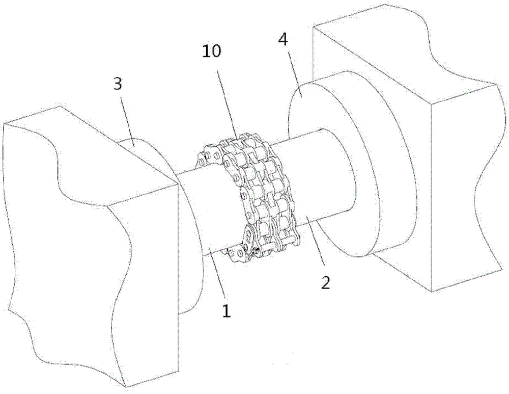
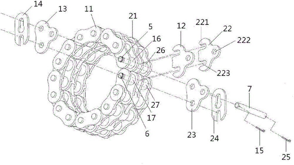
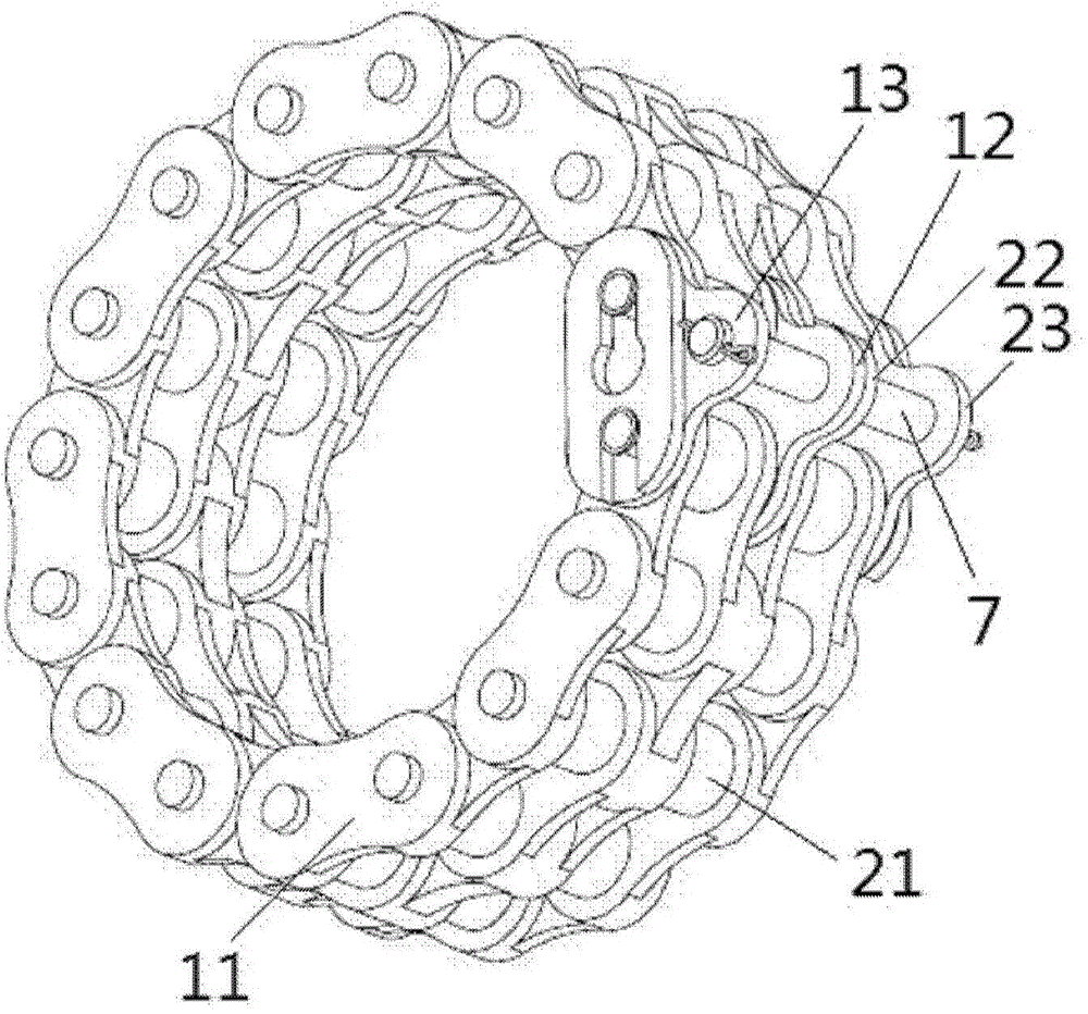
Image

Examples
Embodiment Construction
[0012] Before any embodiments are described in detail, it is to be understood that the invention is not limited in application to the details of construction and the arrangement of parts set forth in the following description or illustrated in the following drawings. The invention is capable of other embodiments and of being practiced or carried out in various ways. Further embodiments of the invention may comprise any combination of features of one or more dependent claims, and such features may be incorporated in any independent claim collectively or individually.
[0013] Exemplary embodiments of the present invention are described in detail below. The exemplary embodiments described herein and illustrated in the drawings are intended to teach the principles of the invention and enable those skilled in the art to implement and use the invention in a number of different environments and for a number of different applications. Accordingly, the exemplary embodiments are not i...
PUM
 Abstract
Description
Claims
Application Information
 - R&D
- Intellectual Property
- Life Sciences
- Materials
- Tech Scout
- Unparalleled Data Quality
- Higher Quality Content
- 60% Fewer Hallucinations
Browse by: Latest US Patents, China's latest patents, Technical Efficacy Thesaurus, Application Domain, Technology Topic, Popular Technical Reports.
© 2025 PatSnap. All rights reserved.Legal|Privacy policy|Modern Slavery Act Transparency Statement|Sitemap|About US| Contact US: help@patsnap.com