Double-gear type wiggler with clearance eliminating function

An oscillator and gear-type technology, applied in the field of oscillators, can solve the problems that the swing fails to meet the requirements, the swing head shakes, and the repair effect of the automatic welding robot on the water cooling wall is affected, so as to improve the repair effect and avoid head swing. shaking effect

Inactive Publication Date: 2016-02-17
HARBIN KENENG CLADDING TECH
View PDF5 Cites 3 Cited by
  • Summary
  • Abstract
  • Description
  • Claims
  • Application Information

AI Technical Summary

Problems solved by technology

[0003] The present invention is to solve the problem that the swinger body of the swinger on the existing fully automatic welding robot adopts an ordinary motor reducer. A gap is generated, which causes the swing head to shake, making the swing not reach the required angle, which affects the effect of the automatic cladding robot on the repair of the water wall. A double-gear swinger with the function of eliminating backlash is provided.

Method used


Image

  • Double-gear type wiggler with clearance eliminating function
  • Double-gear type wiggler with clearance eliminating function
  • Double-gear type wiggler with clearance eliminating function

Examples


specific Embodiment approach 1

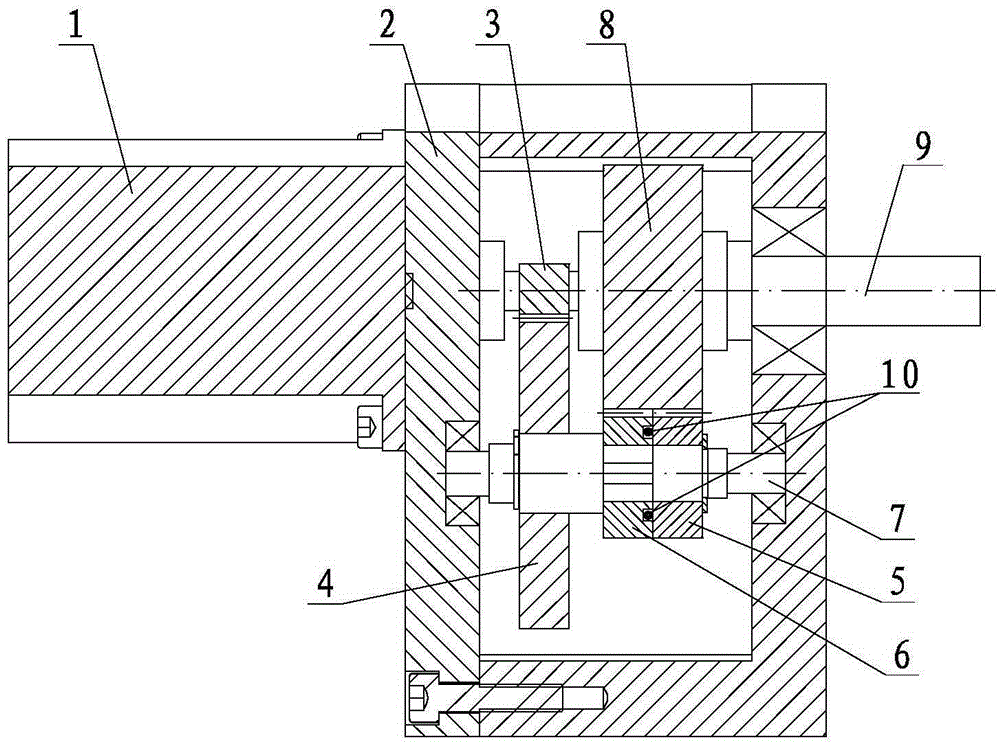
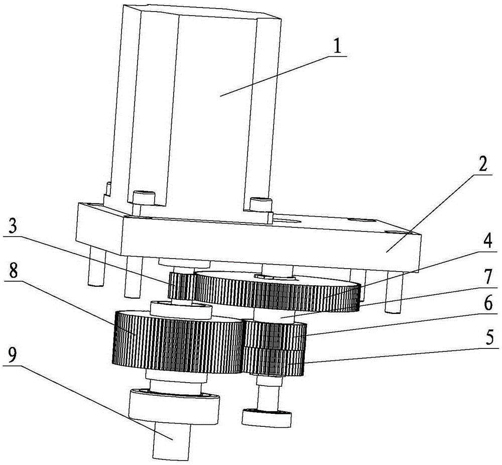
[0012] Specific implementation mode 1: Combination Figure 1 ~ Figure 4 To describe this embodiment, this embodiment includes a motor 1, a housing 2, a primary reduction pinion 3, a primary reduction gear 4, a driving gear 5, an anti-backlash gear 6, a transmission shaft 7, a driven gear 8, and a driven Shaft 9, driven shaft 10, several springs 10 and several pressure blocks 11, the motor 1 is fixed outside the housing 2, and the primary reduction pinion 3 is arranged in the housing 2 and fixed to the output shaft of the motor 1. Above, the primary reduction gear 4 meshes with the primary reduction pinion 3, the primary reduction gear 4, the anti-backlash gear 6 and the driving gear 5 are arranged on the transmission shaft 7 in sequence, the primary reduction gear 4 and the driving gear 5 It is fixedly mounted with the transmission shaft 7, the anti-backlash gear 6 and the transmission shaft 7 are in clearance fit, the driving gear 5 is in contact with the anti-backlash gear 6,...

specific Embodiment approach 2

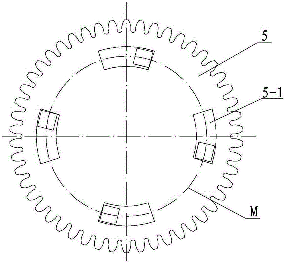
[0013] Specific implementation manner two: combination image 3 with Figure 4 To describe this embodiment, the numbers of the spring 10, the pressure block 11, and the arc-shaped long groove 5-1 in this embodiment are all 2 to 5. When the spring 10 is within the above numerical range, the spring 10 can hold the anti-backlash gear 6 so that the anti-backlash gear 6 rotates with the driving gear 5 while compensating the gap between the driving gear 5 and the driven gear 8, thereby eliminating the driving The gear 5 and the driven gear 8 mesh with a gap. The other components and connection relationships are the same as in the first embodiment.

specific Embodiment approach 3

[0014] Specific implementation mode three: combination image 3 with Figure 4 To describe this embodiment, the numbers of the spring 10, the pressure block 11, and the arc-shaped long groove 5-1 in this embodiment are all four. The four springs 10 are the best values. The anti-backlash gear 6 is held by the spring 10 so that the anti-backlash gear 6 rotates with the driving gear 5 while compensating for the gap between the driving gear 5 and the driven gear 8, thereby eliminating the driving The gear 5 and the driven gear 8 mesh with a gap. Other components and connection relationships are the same as in the second embodiment.

[0015] Working principle: see Figure 5 , The motor 1 drives the primary reduction pinion 3 to rotate, the primary reduction gear 4 rotates and drives the driving gear 5 to rotate, the driving gear 5 and the anti-backlash gear 6 mesh with the driven gear 8 at the same time, and the adjacent ones on the driven gear 8 There is a tooth on the driving gear ...


PUM


Abstract

The invention discloses a double-gear type wiggler with a clearance eliminating function, and aims to solve the problem that a wiggling head wiggles and the wiggling cannot reach a required angle due to the fact that a clearance is generated between a drive gear and a driven gear after the wiggler on a current full-automatic deposition robot works for a long time. A primary reduction large gear, a clearance eliminating gear and the drive gear are sequentially arranged on a transmission shaft; the primary reduction large gear and the drive gear are fixedly connected with a transmission shaft; the clearance eliminating gear and the transmission shaft are in clearance fit; the drive gear is in contact with the clearance eliminating gear; the drive gear and the clearance eliminating gear are engaged with the driven gear; the end surface, facing towards the clearance eliminating gear, of the drive gear is provided with a plurality of circular-arc-shaped long slots along the periphery M; the end surface, facing towards the drive gear, of the clearance eliminating gear is provided with a plurality of pressure blocks along the periphery M; one end of each circular-arc-shaped long slot is provided with a spring; and each spring is fixedly connected with the corresponding pressure block. The double-gear type wiggler is used for the full-automatic deposition robot.

Description

Technical field [0001] The invention relates to an oscillator, in particular to a double-gear oscillator with anti-backlash function. Background technique [0002] The water wall is the main pressure-bearing part of the circulating fluidized bed boiler, which is mainly used to absorb the radiant heat of the boiler. During the operation of the circulating fluidized bed boiler, the solid material flowing down the inner wall of the furnace changes the direction of flow in the junction area, so The surface of the water wall is scoured. After a long time of scouring, the wall of the water wall is worn and thinned and the strength is reduced. In addition, in the transition area, the solid material flowing down the wall is opposite to the upward movement of the solid material in the furnace, and vortexes are generated locally. The swirling flow causes abrasion on the water wall and shortens the service life of the water wall. The fully automatic welding robot is used to repair the worn...

Claims


Application Information

Patent Timeline
Patent Type & Authority Applications(China)
IPC IPC(8): F16H57/12
CPCF16H57/12
Inventor 马洪文王俊明王坤杨晓东严勤朱丽华展乾赵国权
Owner HARBIN KENENG CLADDING TECH
Why Eureka
Try Eureka