Power grid voltage detection circuit
A technology for detecting circuit and grid voltage, applied in the direction of measuring current/voltage, measuring device, measuring electrical variables, etc., can solve the problem of high cost
- Summary
- Abstract
- Description
- Claims
- Application Information
AI Technical Summary
Problems solved by technology
Method used
Image

Examples
Embodiment Construction
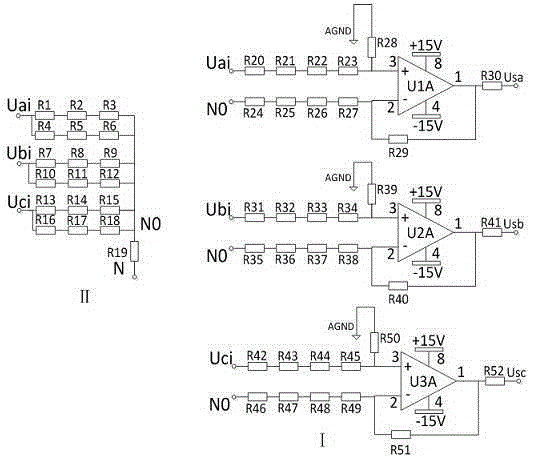
[0015] Such as figure 2 As shown, the invention discloses a grid voltage detection circuit, which includes a three-phase differential voltage detection circuit and a star circuit. The invention includes 3 double operational amplifier chips and 52 patch resistors. The three dual operational amplifier chips U1, U2, and U3 are LM258; the resistor R19 is 0Ω, and the resistors R1 to R18 are all 430KΩ. Resistors R20, R21, R24, R25, R31, R32, R35, R36, R42, R43, R46, R47 are 1MΩ, resistors R22, R26, R33, R37, R44, R48 are 887KΩ, resistors R23, R27, R34, R38 , R45, R49 are 22KΩ, resistors R28, R29, R39, R40, R50, R51 are 34KΩ, R30, R41, R52 are 28KΩ.
[0016] Phase A of the differential sampling detection circuit includes an operational amplifier U1A and 11 resistors R20 to R30. One end of the resistor R20 is connected to the A-phase line Uai of the power grid, and the other end is connected to the resistor R21; the other end of the resistor R21 is connected to the resistor R22; t...
PUM
 Abstract
Description
Claims
Application Information
 - R&D
- Intellectual Property
- Life Sciences
- Materials
- Tech Scout
- Unparalleled Data Quality
- Higher Quality Content
- 60% Fewer Hallucinations
Browse by: Latest US Patents, China's latest patents, Technical Efficacy Thesaurus, Application Domain, Technology Topic, Popular Technical Reports.
© 2025 PatSnap. All rights reserved.Legal|Privacy policy|Modern Slavery Act Transparency Statement|Sitemap|About US| Contact US: help@patsnap.com