Camera position calibration method and device

A calibration method and camera technology, applied in image communication, television, instruments, etc., can solve the problems of inconvenient operation, low information collection efficiency, affecting public safety, etc., and achieve the effect of simplifying operation, improving information collection efficiency, and avoiding influence.

Active Publication Date: 2016-02-17
ZHEJIANG UNIVIEW TECH CO LTD
View PDF10 Cites 22 Cited by
  • Summary
  • Abstract
  • Description
  • Claims
  • Application Information

AI Technical Summary

Problems solved by technology

[0006] The present invention provides a camera position calibration method and device to solve the problem of manual acquisition of camera latitude and longitude information to

Method used


Image

  • Camera position calibration method and device
  • Camera position calibration method and device
  • Camera position calibration method and device

Examples


Embodiment Construction

[0020] In order to enable those skilled in the art to better understand the technical solutions in the embodiments of the present invention, and to make the above-mentioned purposes, features and advantages of the embodiments of the present invention more obvious and understandable, the following describes the technical solutions in the embodiments of the present invention in conjunction with the accompanying drawings For further detailed explanation.

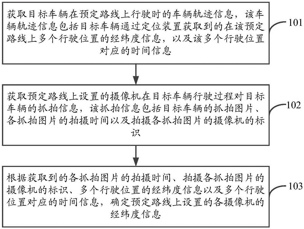
[0021] See figure 1 , figure 1 A schematic flowchart of a camera position calibration method provided by an embodiment of the present invention, as shown in figure 1 As shown, the camera position calibration method may include the following steps:

[0022] Step 101. Obtain the vehicle trajectory information when the target vehicle is driving on the predetermined route, the vehicle trajectory information includes the longitude and latitude information of multiple driving positions on the predetermined route acquired by the tar...


PUM


Abstract

The invention provides a camera position calibration method and a device. The method comprises steps of obtaining vehicle track information of a target vehicle when running on a preset route; obtaining snapshot information of the target vehicle by a camera arranged on the preset route during the running processes of the target vehicle; and determining longitude and latitude information of all cameras arranged on the preset route according to shooting time of each of snapshot pictures, identifications of cameras for shooting the snapshot pictures, the longitude and latitude information in various running positions and time information corresponding to the running positions. In this way, operation of information collection can be simplified; information collection efficiency is increased; and effects on public security during the information collection process can be avoided.

Description

technical field [0001] The invention relates to the technical field of video monitoring, in particular to a camera position calibration method and device. Background technique [0002] The video surveillance technology based on GIS (Geographic Information System, geographic information system) electronic map has been widely used in traffic and public security systems to track illegal vehicles and deal with police situations around the camera. [0003] And use electronic map to monitor, need to demarcate the position of each camera (comprising bayonet camera and electric police camera) on electronic map in advance. However, currently installed cameras generally do not have a GPS (Global Positioning System, Global Positioning System) positioning function, that is, the latitude and longitude information of the cameras cannot be obtained directly. Then the problem of how to obtain the camera position needs to be solved urgently. [0004] The currently adopted solution is gener...

Claims


Application Information

Patent Timeline
IPC IPC(8): G08G1/017H04N7/18
CPCG08G1/017H04N7/181
Inventor 周斌王琳
Owner ZHEJIANG UNIVIEW TECH CO LTD
Why Eureka
Try Eureka