Supercharge Your Innovation With Domain-Expert AI Agents!

electrical connector

A technology of electrical connectors and soldering pins, applied in the direction of connection, fixed connection, circuit, etc., can solve problems such as poor tin coating and inability to repair, and achieve the effect of ensuring electrical connection

Inactive Publication Date: 2018-07-31
立全科技(太仓)有限公司
View PDF6 Cites 0 Cited by
  • Summary
  • Abstract
  • Description
  • Claims
  • Application Information

AI Technical Summary

Problems solved by technology

After soldering to the circuit board, if there are quality factors such as empty soldering and poor tin coating on the soldering feet, it will not be able to be repaired

Method used


Image

  • electrical connector
  • electrical connector
  • electrical connector

Examples


Embodiment Construction

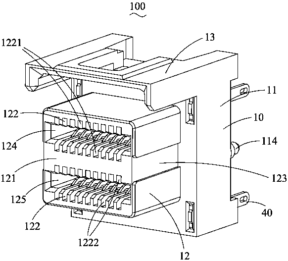
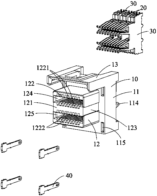
[0026] see figure 1 as well as figure 2 As shown, the illustrated embodiment of the present invention discloses a high-frequency electrical connector 100 , which is used to be welded on a circuit board (not shown) to connect with a mating electrical connector (not shown). The electrical connector 100 includes an insulating body 10, a plurality of signal terminal pairs 20 accommodated in the insulating body 10, a plurality of grounding terminals 30 accommodated in the insulating body 10, and a device mounted on the insulating body 10. 40 slices. The pairs of signal terminals 20 are arranged side by side along the transverse direction of the electrical connector 100 , and the ground terminals 30 are located between adjacent pairs of signal terminals 20 along the transverse direction of the electrical connector 100 .

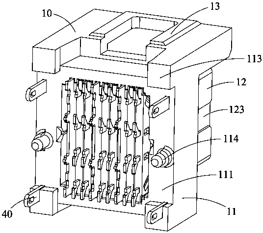
[0027] see figure 1 , figure 2 , image 3 as well as Figure 4 As shown, the insulating housing 10 includes a main body 11 , a docking portion 12 protrudin...


PUM


Abstract

The invention discloses an electrical connector, comprising: an insulating body, several signal terminal pairs and grounding terminals, the insulating body is provided with several terminal receiving grooves, the signal terminal pairs are accommodated in the insulating body, the grounding Terminals are accommodated in the insulating body and located between adjacent pairs of signal terminals along the lateral direction of the electrical connector. The welding foot of the insulating body, the welding foot includes an elongated extension part. Compared with the prior art, the welding leg of the electrical connector of the present invention is provided with an elongated extension, so that when the welding leg of the ground terminal is soldered on the circuit board, the extension will protruding into corresponding welding holes on the circuit board, thereby ensuring the electrical connection between the welding feet and the circuit board.

Description

technical field [0001] The invention relates to an electrical connector, in particular to a high-frequency electrical connector used for soldering on a circuit board. Background technique [0002] Existing high-frequency electrical connectors usually include an insulating body, a pair of differential signal terminals installed in the insulating body, and a ground terminal located between two adjacent pairs of differential signal terminal pairs. When the high-frequency electrical connector is welded to the circuit board by using an SMT welding process, it is necessary to ensure that the welding legs of the high-frequency electrical connector are coplanar. The coplanarity of the solder pins will affect the conduction and transmission functions. For products with four rows of solder feet, the coplanarity of the inner solder feet is not easy to control. The temperature of the inner tin pad is covered by the plastic body above, and the temperature of the tin pad and the tin pla...

Claims


Application Information

Patent Timeline
Patent Type & Authority Patents(China)
IPC IPC(8): H01R12/58H01R13/652
Inventor 游万益郑义宏
Owner 立全科技(太仓)有限公司
Features
  • R&D
  • Intellectual Property
  • Life Sciences
  • Materials
  • Tech Scout
  • Unparalleled Data Quality
  • Higher Quality Content
  • 60% Fewer Hallucinations
Learn More